Procedure: Understanding the Lenovo Storage V7000 Gen1 system status using the LEDs

Use this procedure to determine the Lenovo Storage V7000 Gen1 system status using the LED indicators on the system.

The LEDs provide a general idea of the system status. You can obtain more detail from the management GUI and the service assistant. Examine the LEDs when you are not able to access the management GUI or the service assistant, or when the system is not showing any information about a device.

The procedure shows the status for the enclosure chassis, power supply units and batteries, and canisters. It does not show the status for the drives.

The first step is to determine the state of the control enclosure, which includes its power supply units, batteries, and node canisters. Your control enclosure is operational if you can manage the system using the management GUI. You might also want to view the status of the individual power supply units, batteries, or node canisters.

Find the control enclosure for the system that you are troubleshooting. There is one control enclosure in a system. If you are unsure which one is the control enclosure, follow the procedure to find which enclosure or canister to service.

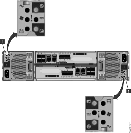
  1. Use the state of the ac power failure, power supply OK, fan failure, and dc power failure LEDs on each power supply unit in the enclosure to determine if there is power to the system, or if there are power problems. Figure 1 shows the LEDs on the power supply unit for the 2076-112 or 2076-124. The LEDs on the power supply units for the 2076-312 and 2076-324 are similar, but they are not shown here.
    Figure 1. LEDs on the power supply units of the control enclosure
    This figure shows the LEDs on the power supply units of the control enclosure.
    Table 1. Power-supply unit LEDs
    Power® supply OK
    This icon shows the power LED on the canister.
    AC failure
    This icon shows the AC power LED on the canister.
    Fan failure
    This icon shows the fan failure LED on the canister.
    DC failure
    This icon shows the DC power LED on the canister.
    Status Action
    On On On On Communication failure between the power supply unit and the enclosure chassis Replace the power supply unit. If failure is still present, replace the enclosure chassis.
    Off Off Off Off No ac power to the enclosure. Turn on power.
    Off Off Off On The ac power is on but power supply unit is not seated correctly in the enclosure. Seat the power supply unit correctly in the enclosure.
    Off On Off On No ac power to this power supply
    1. Check that the switch on the power supply unit is on.
    2. Check that the ac power is on.
    3. Reseat and replace the power cable.
    On Off Off Off Power supply is on and operational. No actions
    Off Off On Off Fan failure Replace the power supply unit.
    Off On On On Communication failure and power supply problem Replace the power supply unit. If replacing the power supply unit does not fix the problem, replace the enclosure chassis.
    Flashing X X X No canister is operational. Both canisters are either off or not seated correctly. Turn off the switch on both power supply units and then turn on both switches. If this action does not resolve the problem, remove both canisters slightly and then push the canisters back in.
    Off Flashing Flashing Flashing Firmware is downloading. No actions. Do not remove ac power.
    Note: In this case, if there is a battery in a power supply unit, its LEDs also flash.
  2. At least one power supply in the enclosure must indicate Power supply OK or Power supply firmware downloading for the node canisters to operate. For this situation, review the three canister status LEDs on each of the node canisters. Start with the power LED.
    Table 2. Power LEDs
    PowerLED status
    This icon shows the power LED on the canister.
    Description
    Off There is no power to the canister. Try reseating the canister. If the state persists, follow the hardware replacement procedures for the parts in the following order: node canister, enclosure chassis.
    Slow flashing (1 Hz) Power is available, but the canister is in standby mode. Try to start the node canister by reseating it.
    Fast flashing (2 Hz) The canister is running its power-on self-test (POST). Wait for the test to complete. If the canister remains in this state for more than 10 minutes, try reseating the canister. If the state persists, follow the hardware replacement procedure for the node canister.
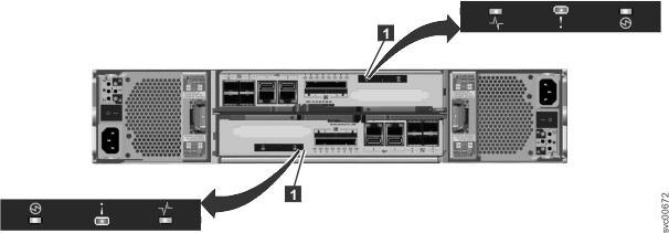
    Figure 2 shows the LEDs on the node canister.
    Figure 2. LEDs on the node canisters
    This figure shows the LEDs on the node canisters.
  3. If the power LED is on, consider the states of the clustered-system status and fault LEDs.
    Table 3. System status and fault LEDs
    System status LED
    The pulse symbol represents the cluster status LED.
    Fault LED
    The exclamation mark represents the fault LED.
    Status
    This icon shows the power LED on the canister.
    Action
    Off Off Code is not active.
    • Follow procedures for reviewing power LEDs.
    • If the power LEDs show green, reseat the node canister. If the LED status does not change, see the topic that contains information about replacing a node canister.
    Off On Code is not active. The BIOS or the service processor has detected a hardware fault. Follow the hardware replacement procedures for the node canister.
    On Off Code is active. Node state is active. No action. The node canister is part of a system and can be managed by the management GUI.
    On On Code is active and is in starting state. However, it does not have enough resources to form the system. The node canister cannot become active in a system. There are no detected problems on the node canister itself. However, it cannot connect to enough resources to safely form a system. Follow the procedure to fix the node errors.
    Flashing Off Code is active. Node state is candidate. Create a system on the node canister, or add the node canister to the system. If the other node canister in the enclosure is in active state, it automatically adds this node canister into the system. A node canister in this state can be managed using the service assistant.
    Flashing On Code is active. Node state is service. The node canister cannot become active in a system. Several problems can exist: hardware problem, a problem with the environment or its location, or problems with the code or data on the canister. Follow the procedure to fix the node errors.
    Any Flashing The node canister is being identified so that you can locate it. The fix procedures in the management GUI might have identified the component because it requires servicing. Continue to follow the fix procedures. The service assistant has a function to identify node canisters. If the identification LED is on in error, use the service assistant node actions to turn off the LED.
To review the status of the control enclosure batteries, see Table 4.
Table 4. Control enclosure battery LEDs
Battery Good
This icon shows the battery charge LED on the node canister.
Battery Fault
This icon shows the battery status LED on the node canister.
Description Action
On Off Battery is good and fully charged. None
Flashing off Battery is good but not fully charged. The battery is either charging or a maintenance discharge is in process. None
Off On Nonrecoverable battery fault. Replace the battery. If replacing the battery does not fix the issue, replace the power supply unit.
Off Flashing Recoverable battery fault. None
Flashing Flashing The battery cannot be used because the firmware for the power supply unit is being downloaded. None