Ethernet ports are located side by side on the rear of the node canister. All control enclosure models have two 1 Gbps Ethernet ports per node canister. Model 2076-312 and model 2076-324 also have two 10 Gbps Ethernet ports per node canister.
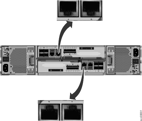
For the 1 Gbps support, the Ethernet ports are numbered 1 on the left and 2 on the right as shown in Figure 1. Port 1 must be connected; the use of port 2 is optional. Two LEDs are associated with each port.
Note: The reference to
the left and right locations applies to canister 1, which is the upper canister. The port locations are inverted for canister 2, which is the
lower canister.
Figure 1. Ethernet ports on the 2076-112 and 2076-124 node canisters


Table 1 provides a description of the two LEDs.
| Name | Description | Color |
|---|---|---|
| Link speed (LED on right of upper canister) | The LED is on when there is a link connection; otherwise, the LED is off. | Green |
| Activity (LED on left of upper canister) | The LED is flashing when there is activity on the link; otherwise, the LED is off. | Yellow |
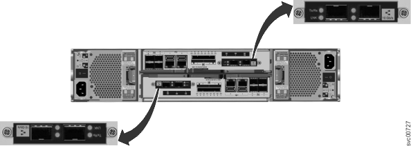
Figure 2 shows
the location of the 10 Gbps Ethernet ports.
Figure 2. 10 Gbps Ethernet ports on the 2076-312 and 2076-324 node canisters


Table 2 provides
a description of the LEDs.
| Name | Symbol | Description | Color |
|---|---|---|---|
| Activity | Tx/Rx | The LED is flashing when there is activity on the link; otherwise, the LED is off. | Green |
| Link | LNK | The LED is on when there is a link connection; otherwise, the LED is off. | Amber |