Replacing a Lenovo Storage V7000 Gen2 control enclosure midplane assembly

A trained service provider can use this procedure to replace a faulty Lenovo Storage V7000 Gen2 control enclosure midplane with a new one received from CRU / FRU stock. Ensure that your control enclosure midplane assembly is replaced only by a trained service provider.

Three persons are required at step 14.

Follow all safety precautions when completing this procedure.

DANGER
When working on or around the system, observe the following precautions:

Electrical voltage and current from power, telephone, and communication cables are hazardous. To avoid a shock hazard:

  • If Lenovo supplied a power cord(s), connect power to this unit only with the Lenovo provided power cord. Do not use the Lenovo provided power cord for any other product.
  • Do not open or service any power supply assembly.
  • Do not connect or disconnect any cables or perform installation, maintenance, or reconfiguration of this product during an electrical storm.
  • The product might be equipped with multiple power cords. To remove all hazardous voltages, disconnect all power cords.
  • Connect all power cords to a properly wired and grounded electrical outlet. Ensure that the outlet supplies proper voltage and phase rotation according to the system rating plate.
  • Connect any equipment that will be attached to this product to properly wired outlets.
  • When possible, use one hand only to connect or disconnect signal cables.
  • Never turn on any equipment when there is evidence of fire, water, or structural damage.
  • Disconnect the attached power cords, telecommunications systems, networks, and modems before you open the device covers, unless instructed otherwise in the installation and configuration procedures.
  • Connect and disconnect cables as described in the following procedures when installing, moving, or opening covers on this product or attached devices.
    To disconnect:
    1. Turn off everything (unless instructed otherwise).
    2. Remove the power cords from the outlets.
    3. Remove the signal cables from the connectors.
    4. Remove all cables from the devices.
    To connect:
    1. Turn off everything (unless instructed otherwise).
    2. Attach all cables to the devices.
    3. Attach the signal cables to the connectors.
    4. Attach the power cords to the outlets.
    5. Turn on the devices.
  • Sharp edges, corners and joints might be present in and around the system. Use care when handling equipment to avoid cuts, scrapes and pinching.
Attention:

The control enclosure must be replaced only by a trained service provider. Complete this procedure only if instructed to do so by a service action or the IBM support center.

If you have a single control enclosure, this procedure requires that you shut down your system to replace the control enclosure midplane assembly. If you have more than one control enclosure, you can keep part of the system running, but you lose access to the volumes that are on the affected I/O group and any volumes that are in other I/O groups that depend on the drives that are in the affected I/O group. If the system is still doing I/O requests in all the I/O groups, schedule the replacement during a maintenance period or other time when the I/O can be stopped.

When replacing hardware components in the back of the enclosure, ensure that you do not inadvertently disturb or remove cables that you are not instructed to remove.

Ensure that you are aware of procedures for handling static-sensitive devices before you remove the enclosure.

To replace the control enclosure midplane, complete the following steps:

  1. Log in to the service assistant on one of the node canisters in the control enclosure.
  2. Navigate to the Enclosure Information panel.
    Important: Do NOT select the Reset the system ID check box.
    Record the following information for use in subsequent steps:
    • WWNN 1
    • WWNN 2
    • Machine type and model
    • Serial number
  3. Read the safety information in Preparing to remove and replace parts.
  4. If the control enclosure is still active, stop host I/O and Metro Mirror and Global Mirror activity on all the volumes that depend on the enclosure
    This step applies to all I/O group volumes that are managed by this enclosure plus any volumes in other I/O groups that depend on the drives in the affected I/O group.
  5. Complete Procedure: Powering off a Lenovo Storage V7000 Gen2 control enclosure for the control enclosure that requires the midplane assembly replacement.
  6. Disconnect both power cables from the rear of the enclosure.
  7. Write down which port connects to which cable before disconnecting all cables from the rear of the enclosure.
  8. Carefully remove each drive and label it with the drive slot from which it was removed.

    You can use the drive-slot information to insert the drives into the correct drive slots at the end of this procedure.

  9. Remove the two power supplies from the enclosure. Refer to Replacing a Lenovo Storage V7000 Gen2 power supply unit for a control enclosure for guidance.
  10. Remove the node canisters from the enclosure. Label them to indicate what canister came from each canister slot.
  11. Remove the fan modules from the enclosure, as described in Replacing a Lenovo Storage V7000 Gen2 fan module.
  12. Remove the end caps from the enclosure, as described in Replacing Lenovo Storage V7000 Gen2 enclosure end caps.
  13. Remove the two M5 screws from the front of the enclosure to free the enclosure from the rack.
  14. Slide the enclosure from the rack, and then place the enclosure on a work surface, so that the underside of the enclosure faces upward, and the enclosure front is facing toward you.
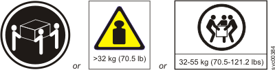
    CAUTION:

    Two graphics show 3 persons carrying a heavy box; one graphic shows an icon with text warning that weight i s more than 32 kg (70.5 lb)
    The weight of this part or unit is between 32 and 55 kg (70.5 and 121.2 lb). It takes three persons to safely lift this part or unit. (C010)
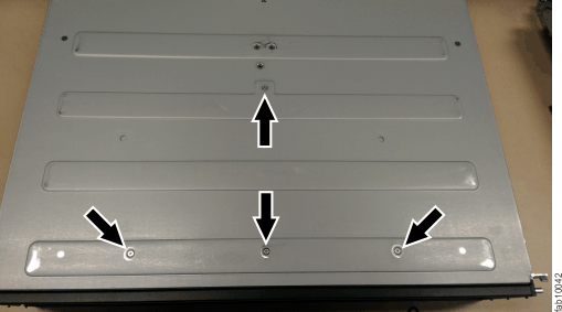
  15. Remove the four screws from the bottom of the enclosure. Three screws are near the front and one is near the middle. Label these screws to indicate the location from which they are removed and place them aside.
    Figure 1 illustrates the location of the screws on the bottom of the enclosure.
    Figure 1. Bottom enclosure screws
    Bottom enclosure screws
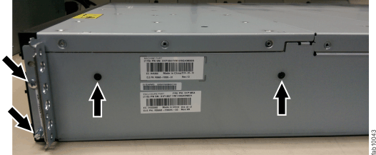
    Note: A PH1 screw driver is used for the screws in this step and the following steps. A pair of pliers is needed for the screw-pins in the following steps.
  16. Turn the enclosure over again so that the top of the enclosure is facing upward and the front is facing towards you.
  17. Remove the three screws and one screw-pin on the right side that secure the midplane assembly to the enclosure. Label each screw to indicate the removal location and place the screws aside.
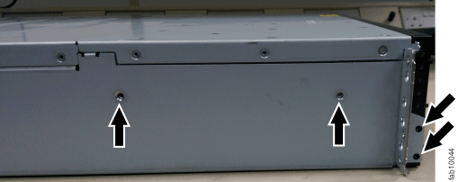
    Figure 2 illustrates the location of the screws and screw-pin on the right-side of the enclosure.
    Figure 2. Right-side enclosure screws
    Right-side enclosure screws
  18. Remove the three screws and one screw-pin on the left side that secure the midplane assembly to the enclosure. Label each screw to indicate the removal location and place the screws aside.
    Figure 3 illustrates the location of the screws and screw-pin on the left-side of the enclosure.
    Figure 3. Left-side enclosure screws
    Left-side enclosure screws
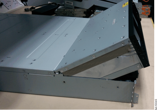
  19. Remove the midplane assembly from the chassis by rotating up the midplane assembly to about 45°, then withdraw the midplane assembly from the front of the enclosure.
    Figure 4 shows the midplane assembly at a 45 degree angle.
    Figure 4. Angled midplane assembly
    Angled midplane assembly
  20. Unpack the replacement midplane assembly. Grasp the midplane assembly with two hands to hold the assembly at a 45° angle.
  21. Insert the tabs on the midplane assembly into the tab holes in the enclosure and rotate down the front of the assembly.
  22. Secure the midplane assembly to the enclosure chassis on both the right and left sides using six screws and two screw-pins that you removed in steps 16 and 17.
  23. Turn over the bottom of the enclosure to face upward, then insert the four screws on the bottom of the enclosure that were removed in step 15.
  24. Reinstall the enclosure in the rack cabinet, securing it with two screws that were removed at step 13.
  25. Reinstall the end caps at the front of the enclosure, as described in Replacing Lenovo Storage V7000 Gen2 enclosure end caps.
  26. Reinstall the hard disk drives at the front of the enclosure, making sure that each drive is inserted into the same slot from which it was removed.
  27. Replace the fan modules, as described in Replacing a Lenovo Storage V7000 Gen2 fan module.
  28. Reinstall the canisters into the same canister slots from which you removed them.
  29. Reinstall the two power supplies.
  30. Reconnect the data cables at the rear of the enclosure into the same connectors from which you removed them.
  31. Reconnect power to the control enclosure.
    The node canisters restart. The fault LEDs are on because the new enclosure has not been set with the identity of the old enclosure. The node canisters log node error 504, reporting that they are in the wrong location. In the system event log, the error code is 1192.
  32. Connect to the service assistant on one of the node canisters to configure the machine type and model, serial number, and WWNNs that are stored in the enclosure.
    If you have replaced a node canister, connect to the canister that has not been replaced.
    The service assistant retains a copy of the same information that was on the faulty enclosure midplane assembly. You can connect using the previous service address. However, it is not always possible to maintain this address. If you cannot connect through the original service address, attempt to connect using the default service address. If you still cannot access the system, see Problem: Cannot connect to the service assistant.
  33. Use the Configure enclosure panel.
  34. Use the node copy data that you recorded in step 2 to update each of these values: Update WWNN 1, Update WWNN 2, Update the machine type and model, and Update the serial number.
    Attention: Do not update the system ID.
    If you were not able to record the values, use the node copy values only if none of them have all zeros as their value. If any of the node copy values are all zeros, connect the service assistant to the other node canister and configure the enclosure there. If you still do not have a full set of values, contact IBM support.
    Important: Step 35 writes the enclosure identity into the replacement midplane. The replacement midplane cannot be used as a replacement part for a different enclosure after step 35 is completed.
  35. In the Enclosure Information panel, click Modify. The node canisters restart. When the restart finishes, the system comes online with both node canisters online.
    Note: In some situations, the canisters restart and report critical node error 508. If the node canisters fail to become active after they restart when the enclosure is updated, check their status by using the service assistant. If both node canisters show critical node error 508, use the service assistant to restart the nodes. For any other node error, see Procedure: Fixing node errors. To restart a node from the service assistant, complete the following steps:
    1. Log on to the service assistant.
    2. From the home page, select the node that you want to restart from the Changed Node List.
    3. Select Actions > Restart.
    The system starts and can handle I/O requests from any host systems.
  36. Use the management GUI to check the status of all volumes and physical storage to ensure that everything is online.
  37. Go to Monitoring > Events to check the event log for other events or errors.
  38. Restart the host application and any FlashCopy activities, Global Mirror activities, or Metro Mirror activities that were stopped.