Use this information to install a 8x 2.5-inch hot-swap HDD assembly kit with expander.
You can install a Lenovo Storage DX8200 8x 2.5-inch hot-swap HDD assembly with expander kit to add eight additional 2.5-inch hot-swap hard disk drives in the server. See the Lenovo ServerProven website for a list of supported optional devices. To order a 8x 2.5-inch hot-swap HDD assembly kit with expander, contact your sales representative or reseller.
The 8x 2.5-inch hot-swap HDD assembly with expander kit contains
the following components:
- Eight 2.5-inch HDD fillers
- One expander
- Two power/configuration cables (230 mm)
- One power/configuration cable (260 mm)
- One Mini-SAS HD Y-cable (580/590 mm)
- One Mini-SAS HD cable (350 mm)
- One Mini-SAS HD cable (150 mm)
- Two Mini-SAS HD cables (250 mm)
Note: The 8x 2.5-inch hot-swap HDD assembly with expander kit
including structural parts and Tier 1 parts.
To install a 8x 2.5-inch hot-swap HDD assembly with expander kit, complete the following steps:
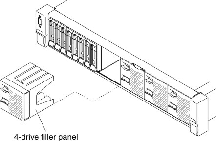
- Remove the two 4-drive filler panels.
Figure 1. Filler panels
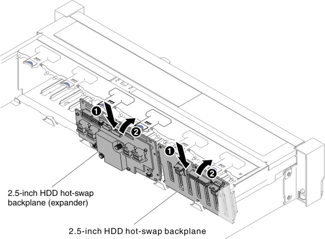
- Install the new backplane in slot 2 or slot 3 depending
on your configuration. Insert the backplane tabs into slots on the
bottom of the cage and push the backplane forward into the release
latch (on top of the backplane cage) until the backplane is locked
in place.
Note: You can connect the cables to the drive backplane before installing the backplane onto the cage or you can connect the cables after you install the backplane, if that is easier for you.Figure 2. Expander installation
- Connect Mini-SAS HD cables, power/configuration and Mini-SAS
HD Y-cable which come with the option kit to the backplanes and the
system board.
- If you are installing the new expander in slot 2, connect and
route cables as the following illustrations.Figure 3. Cable connections
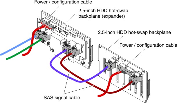
Figure 4. Cable routing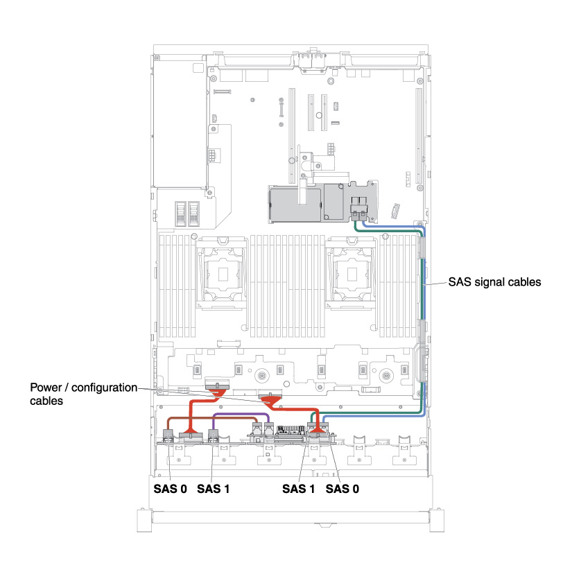
- If you are installing the new expander in slot 3, connect and
route cables as the following illustrations.
- If the backplane is installed in slot 2, connect and route cables
as the following illustrations.Figure 5. Cable connections
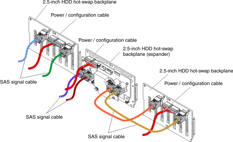
Figure 6. Cable routing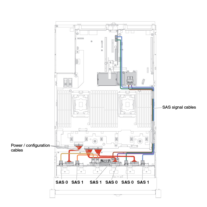
- If the expander is installed in slot 2, connect and route cables
as the following illustrations.Figure 7. Cable connections
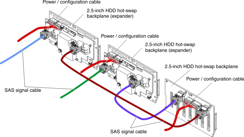
Figure 8. Cable connections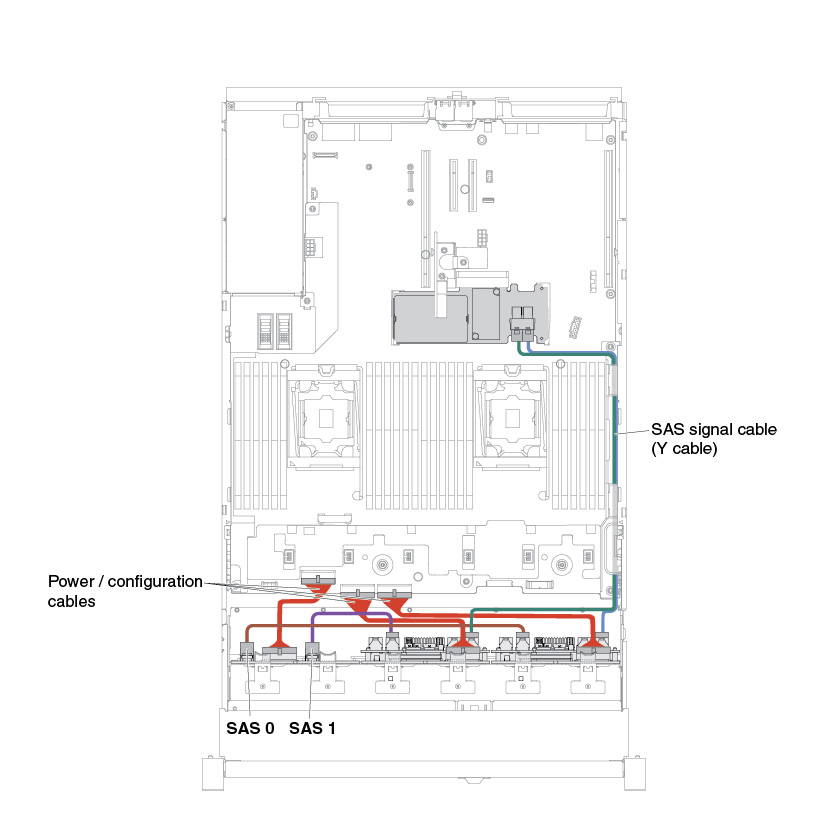
- If the backplane is installed in slot 2, connect and route cables
as the following illustrations.
- If you are installing the new expander in slot 2, connect and
route cables as the following illustrations.