Use this information to install a 4x 2.5-inch NVMe PCIe SSD upgrade kit.
To order a 4x 2.5-inch NVMe PCIe SSD upgrade kit, contact your sales representative or reseller.
The 4x 2.5-inch NVMe
PCIe SSD upgrade kit contains the following components:
- Four signal cables
- One power/configuration cable
- One backplane assembly
To install the 4x 2.5-inch NVMe PCIe SSD upgrade kit in the server, complete the following steps.
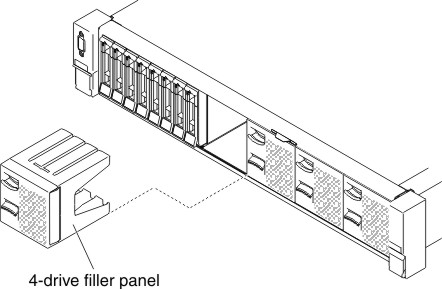
- Remove the two 4-drive filler panels according to your
configuration.
Figure 1. Filler panels
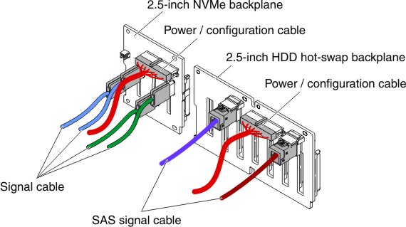
- Connect the power/configuration and signal cables to the
backplane.
- 8x 2.5-inch HDD + 4x 2.5-inch NVMe PCIe SSDFigure 2. Cable connections
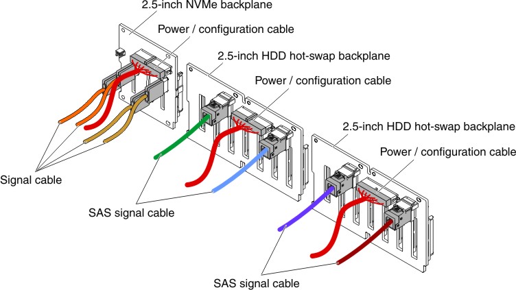
- 16x 2.5-inch HDD + 4x 2.5-inch NVMe PCIe SSDFigure 3. Cable connections
- 8x 2.5-inch HDD + 4x 2.5-inch NVMe PCIe SSD
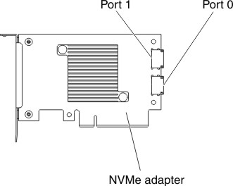
- Connect the four signal cables to the connectors on the
NVMe adapter:
Figure 4. NVMe adapter connectors
- Route the cables underneath the cable retention.
- 8x 2.5-inch HDD + 4x 2.5-inch NVMe PCIe SSDFigure 5. Cable routing
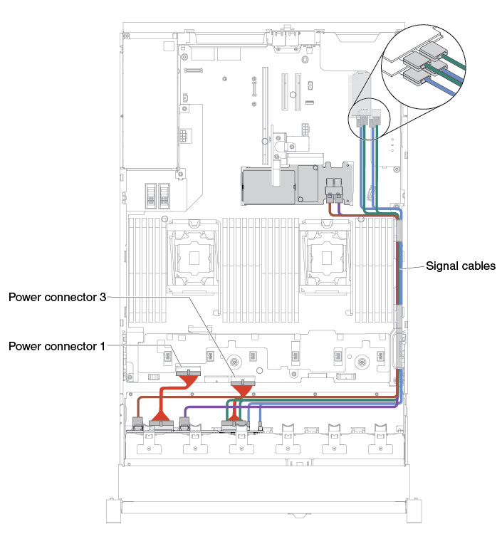
Note:- For the power cable connection, the NVMe backplane can only connect to the power connector 3.
- There might be 3 or 4 power connectors on the system board depending on your configuration. However, this difference will not affect the cable routing. Follow the following illustrations to complete your cable routing.
- 16x 2.5-inch HDD + 4x 2.5-inch NVMe PCIe SSDFigure 6. Cable routing
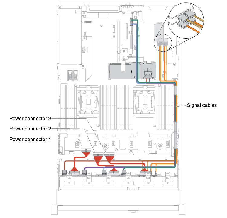
Note:- For the power cable connection, the NVMe backplane can only connect to the power connector 3.
- There might be 3 or 4 power connectors on the system board depending on your configuration. However, this difference will not affect the cable routing. Follow the following illustrations to complete your cable routing.
- 8x 2.5-inch HDD + 4x 2.5-inch NVMe PCIe SSD