Removing the system board

Use this information to remove the system board.

Note:
  1. When you replace the system board, you must either update the server with the latest firmware or restore the pre-existing firmware that the customer provides on a diskette or CD image. Make sure that you have the latest firmware or a copy of the pre-existing firmware before you proceed.
  2. When you replace the system board, make sure that you remove the Integrated Management Module Advanced Upgrade and place it on the new system board. For information about the Advanced Upgrade, see Using the remote presence and blue-screen capture features.
  3. Before you replace the system board, make sure that you back up any features on demand (FoD) keys that were enabled. Reactivate any Features on Demand features. Instructions for automating the activation of features and installing activation keys is in the Features on Demand User's Guide. To download the document, go to the Lenovo Features on Demand website, log in, and click Help.

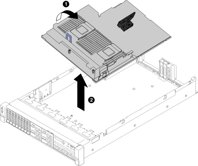
To remove the system board, complete the following steps:

  1. Read the safety information that begins on Safety, Handling static-sensitive devices, and Installation guidelines.
  2. Turn off the server and any attached devices.
  3. Turn off the peripheral devices and disconnect all power cords.
    Note: When you replace the system board, you must either update the server with the latest firmware or restore the pre-existing firmware that the customer provides on a diskette or CD image. Make sure that you have the latest firmware or a copy of the pre-existing firmware before you proceed.
  4. Pull the power supplies out of the rear of the server, just enough to disengage them from the server.
  5. Remove the top cover (see Removing the top cover).
  6. Remove all PCI riser-card assemblies and adapters (see Removing a riser-card assembly and Removing an adapter).
  7. Remove the air baffle (see Removing the air baffle).
  8. Remove the fan cage assembly (See Removing the fan cage assembly).
  9. Remove any backplate assembly or any backplane (See Removing the 2.5-inch simple-swap backplate assembly/hot-swap hard disk drive backplane and Removing the 3.5-inch simple-swap backplate assembly/hot-swap hard disk drive backplane).
  10. Remove the dedicate slotless RAID controller (see Removing the dedicated slotless RAID controller).
  11. Remove the paddle card module (see Removing the power paddle module).
  12. Remove the memory modules and set them aside on a static-protective surface for reinstallation (see Removing a memory module).
    Note: Make a note of the location of each DIMM as you remove it, so that you can later reinstall it in the same connector.
  13. (Trained technician only) Remove all heat sinks and microprocessors, and set them aside on a static-protective surface for reinstallation (see Removing a microprocessor and heat sink).
    Note: Do not allow the thermal grease to come in contact with anything, and keep each heat sink paired with its microprocessor for reinstallation. Contact with any surface can compromise the thermal grease and the microprocessor socket. A mismatch between the microprocessor and its original heat sink can require the installation of a new heat sink.
  14. Disconnect all cables from the system board. Make a list of each cable as you disconnect it; you can then use this as a checklist when you install the new system board (see Internal cable routing and connectors for more information).
    Attention: Disengage all latches, release tabs or locks on cable connectors when you disconnect all cables from the system board. Failing to release them before removing the cables will damage the cable sockets on the system board. The cable sockets on the system board are fragile. Any damage to the cable sockets may require replacing the system board.
  15. 1 Loosen the two thumbscrews (located near the front of the server) that secure the system board to the server and 2 slide the system board toward the front of the server.
  16. Grasp both system-board handles and lift up the left side of the system board slightly and carefully remove it from the chassis, being careful not to damage any surrounding components.
    Note: Use the system-board handles to lift the system board only. Do not attempt to lift the server using the system board handles.
    Figure 1. System board removal
    System board removal
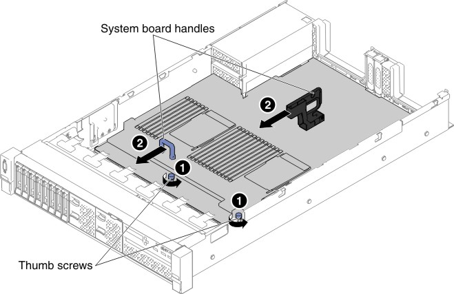
  17. 1 Push the system board toward the broadside of the server and 2 lift the system board up.
    Figure 2. System board removal
    System board removal
  18. If you are instructed to return the system board, follow all packaging instructions, and use any packaging materials for shipping that are supplied to you.
    Attention: Make sure to place the socket covers for the microprocessor sockets on the system board before returning the system board.