Use this information to remove a microprocessor and heat sink.
Microprocessors are to be removed only by trained technicians.
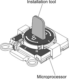
Important: Always use the microprocessor installation tool to remove a microprocessor. Failing to use the microprocessor installation tool may damage the microprocessor sockets on the system board. Any damage to the microprocessor sockets may require replacing the system board.
Do not allow the thermal grease on the microprocessor and heat sink to come in contact with anything. Contact with any surface can compromise the thermal grease and the microprocessor socket.
Dropping the microprocessor during installation or removal can damage the contacts.
Do not touch the microprocessor contacts; handle the microprocessor by the edges only. Contaminants on the microprocessor contacts, such as oil from your skin, can cause connection failures between the contacts and the socket.
Installation tool has two settings for installing two different sizes of microprocessors. The settings that are marked on the tool are "L" for smaller low core microprocessors, and "H" for larger high core microprocessors.
To remove a microprocessor and heat sink, complete the following steps:
- Remove the heat sink.
Attention: Do not touch the thermal material on the bottom of the heat sink. Touching the thermal material will contaminate it. If the thermal material on the microprocessor or heat sink becomes contaminated, you must wipe off the contaminated thermal material on the microprocessor or heat sink with the alcohol wipes and reapply clean thermal grease to the heat sink.
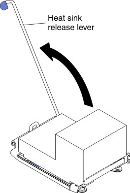
- Open the heat sink retention module release lever to
the fully open position.
Figure 2. Heat sink retention module release lever
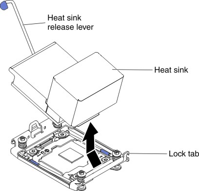
- Lift the heat sink out of the server. After removal,
place the heat sink (with the thermal grease side up) on a clean,
flat surface.
Figure 3. Heat sink removal
- Open the heat sink retention module release lever to
the fully open position.
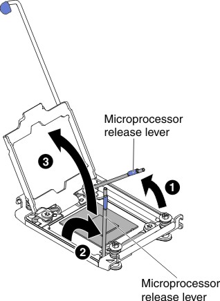
- Open the microprocessor socket release levers and retainer.
Figure 4. Microprocessor socket levers and retainer disengagement
- Remove the microprocessor from the socket.
- Select the empty installation tool and ensure that the
handle is in the unlocked position. If the installation tool handle
is not in the unlocked position, use the following instructions for
your installation tool:
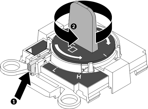
- 1 lift the interlock latch and hold it up while you 2 twist the microprocessor installation tool handle counterclockwise
to the unlocked position, and then release the interlock latch. The
following illustration of the installation tool shows the location
of the interlock latch and counterclockwise rotation of the handle
before loading the microprocessor.Figure 5. Installation tool handle adjustment
The following illustrations show the installation tool in the locked and unlocked positions.Figure 6. Locked and unlocked positions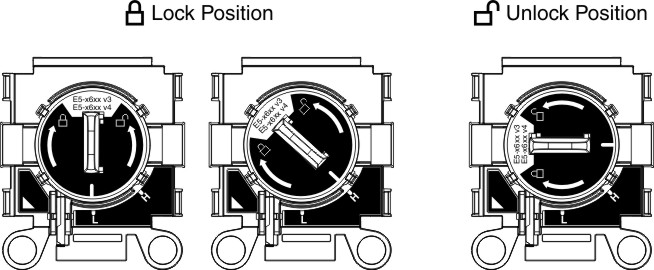
- 1 lift the interlock latch and hold it up while you 2 twist the microprocessor installation tool handle counterclockwise
to the unlocked position, and then release the interlock latch. The
following illustration of the installation tool shows the location
of the interlock latch and counterclockwise rotation of the handle
before loading the microprocessor.
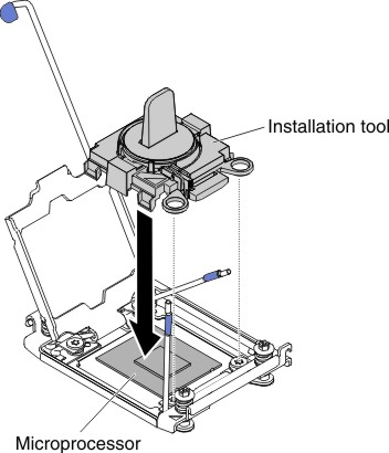
- Align the installation tool with the screws, as shown
in the following graphic, and lower the installation tool on the microprocessor.
The installation tool rests flush on the socket only when it is aligned
correctly.
Figure 7. Installation tool alignment
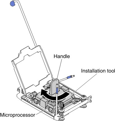
- To remove the microprocessor, gently twist the handle
of the installation tool clockwise until it locks in the "H" or "L" position, depending on the size of microprocessor, and then
lift the microprocessor out of the socket.
Figure 8. Installation tool handle adjustment
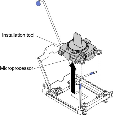
- Lift the microprocessor out of the socket.
Figure 9. Installation tool removal
- Select the empty installation tool and ensure that the
handle is in the unlocked position. If the installation tool handle
is not in the unlocked position, use the following instructions for
your installation tool: