Use this information to replace a microprocessor and heat sink.
The following notes describe the type of microprocessor that the server supports and other information that you must consider when you install a microprocessor and heat sink:
Microprocessors are to be installed only by trained technicians.
Important: Always use the microprocessor installation tool to install a microprocessor. Failing to use the microprocessor installation tool may damage the microprocessor sockets on the system board. Any damage to the microprocessor sockets may require replacing the system board.
- The server supports up to two Intel Xeon™ E5-2600 v4 series multi-core microprocessors, which are designed for the LGA 2011 socket. See the Lenovo ServerProven website for a list of supported microprocessors.
- Do not mix microprocessors with different cores in the same server.
- The first microprocessor must always be installed in microprocessor socket 1 on the system board.
- When one microprocessor is installed, the air baffle must be installed to provide proper system cooling.
- Do not remove the first microprocessor from the system board when you install the second microprocessor.
- When you install the second microprocessor, you must also install additional memory and the fourth fan. See Installing a memory module for details about the installation sequence.
- To ensure proper server operation when you install an additional microprocessor, use microprocessors that have the same QuickPath Interconnect (QPI) link speed, integrated memory controller frequency, core frequency, power segment, internal cache size, and type.
- Mixing microprocessors of different stepping levels within the same server model is supported.
- When mixing microprocessors with different stepping levels within the same server model, you do not have to install the microprocessor with lowest stepping level and features in microprocessor socket 1.
- Both microprocessor voltage regulator modules are integrated on the system board.
- Read the documentation that comes with the microprocessor to determine whether you have to update the server firmware. To download the latest level of server firmware and other code updates for your server, go to the Lenovo Support Portal.
- The microprocessor speeds are automatically set for this server; therefore, you do not have to set any microprocessor frequency-selection jumpers or switches.
- If the thermal-grease protective cover (for example, a plastic
cap or tape liner) is removed from the heat sink, do not touch the
thermal grease on the bottom of the heat sink or set down the heat
sink. For more information about applying or working with thermal
grease, see Thermal grease. Note: Removing the heat sink from the microprocessor destroys the even distribution of the thermal grease and requires replacing the thermal grease.
- To order an additional optional microprocessor, contact your sales representative or reseller.
Installation tool has two settings for installing two different sizes of microprocessors. The settings that are marked on the tool are "L" for smaller low core microprocessors, and "H" for larger high core microprocessors.
To replace a microprocessor and heat sink, complete the following steps:
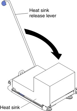
- Rotate the heat sink retention module release lever to
the open position.
Figure 2. Heat-sink lever rotation
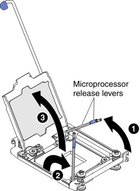
- Open the microprocessor socket release levers and retainer:
Figure 3. Microprocessor socket levers and retainer disengagement
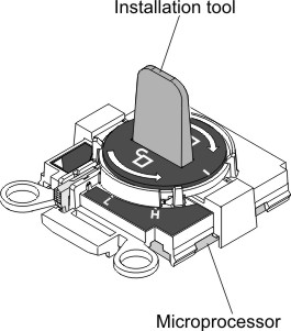
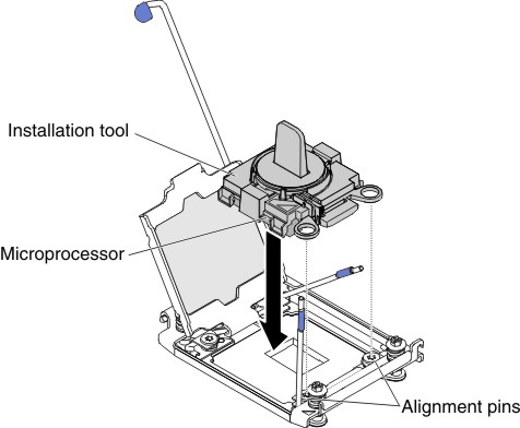
- Install the microprocessor on the microprocessor socket:
- Align the installation tool with the microprocessor
socket and lower down the installation tool. The installation tool
rests flush on the socket only if properly aligned.
Figure 4. Installation tool alignment
- Install the microprocessor using the following instructions
for your installation tool.
- Twist the handle of the installation tool assembly counterclockwise to the unlocked position until you can not twist the handle any further; then, lift the installation tool out of the socket.
Figure 5. Installation tool handle adjustment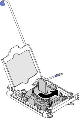
The following illustrations show the installation tool in the locked and unlocked positions.Figure 6. Installation tool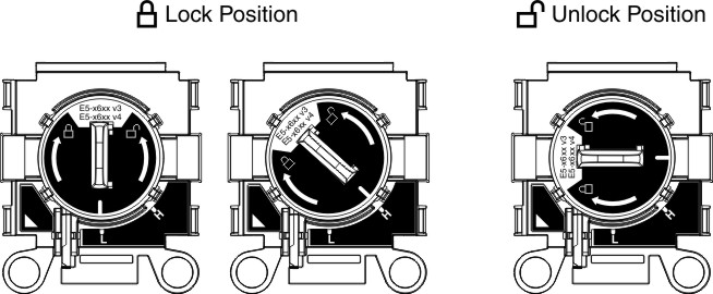
Figure 7. Installation tool removal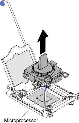
Attention:- Do not press the microprocessor into the socket.
- Make sure that the microprocessor is oriented and aligned correctly in the socket before you try to close the microprocessor retainer.
- Do not touch the thermal material on the bottom of the heat sink or on top of the microprocessor. Touching the thermal material will contaminate it.
- Align the installation tool with the microprocessor
socket and lower down the installation tool. The installation tool
rests flush on the socket only if properly aligned.
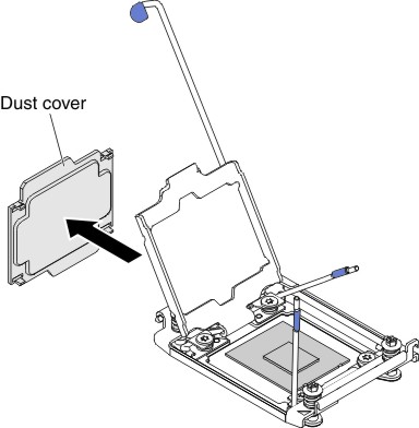
- Remove the cover from the retainer bracket,
if one is present. Store the cover in a safe place.
Figure 8. Socket cover removal
Attention: When you handle static-sensitive devices, take precautions to avoid damage from static electricity. For details about handling these devices, see Handling static-sensitive devices. - Close the microprocessor socket release levers and retainer:
Figure 9. Microprocessor socket levers and retainer engagement
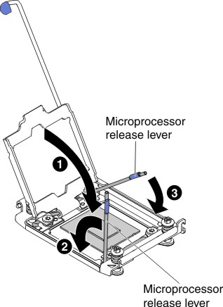
- Close the microprocessor retainer on the microprocessor socket.
- Identify which release lever is labeled as the first release lever to close and close it.
- Close the second release lever on the microprocessor socket.
- Install the heat sink.
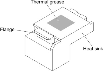
Attention:
- Do not set down the heat sink after you remove the plastic cover.
- Do not touch the thermal grease on the bottom of the heat sink
after you remove the plastic cover. Touching the thermal grease will
contaminate it. See Thermal grease for more information. Figure 10. Thermal grease
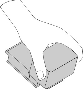
- Grasp the heat sink firmly as the following illustration
to avoid possible damage to the heat sink.
Figure 11. Heat sink
- Position the heat sink over the microprocessor. The
heat sink is keyed to assist with proper alignment.
Figure 12. Heat sink installation
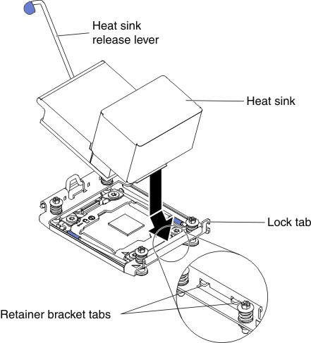
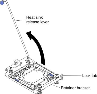
- Rotate the heat sink retention module release lever
to the closed position and hook it underneath the lock tab.
Figure 13. Heat sink retention module release lever