Installing an optional DVD drive
Use this information to install an optional DVD drive.
The following notes describe the type of drives that the server supports and other information that you must consider when you install a hard disk drive.
- Locate the documentation that comes with the drive and follow those instructions in addition to the instructions in this chapter.
- Make sure that you have all the cables and other equipment that are specified in the documentation that comes with the drive.
- The server supports one ultra-slim SATA optical drive.
If you need to install an optional DVD drive, complete the following steps:
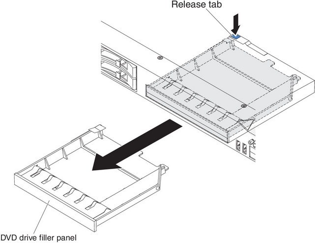
- Remove the DVD drive filler panel if it is installed. locate the blue release tab on the rear of the DVD drive filler panel; then, while you press the tab, push the DVD drive filler panel out of the drive bay. Figure 1. DVD drive filler panel removal
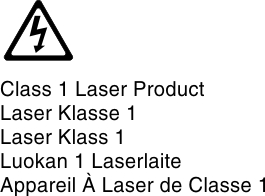
- Remove the retention clip from the side of the DVD drive filler panel. Save the DVD drive filler panel for future use.NoteIf you are installing an optical drive that contains a laser, observe the following safety precaution.Statement 3
 CAUTIONWhen laser products (such as CD-ROMs, DVD drives, fiber optic devices, or transmitters) are installed, note the following:
- Do not remove the covers. Removing the covers of the laser product could result in exposure to hazardous laser radiation. There are no serviceable parts inside the device.
- Use of controls or adjustments or performance of procedures other than those specified herein might result in hazardous radiation exposure.
DANGERdangerSome laser products contain an embedded Class 3A or Class 3B laser diode. Note the following.Laser radiation when open. Do not stare into the beam, do not view directly with optical instruments, and avoid direct exposure to the beam.
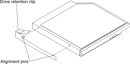
- Attach the drive retention clip that you removed from the DVD drive filler panel to the side of the new DVD drive.Figure 2. DVD drive retention clip installation
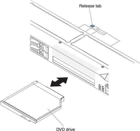
- Align the DVD drive in the drive bay and slide the DVD drive into the optical drive bay until the DVD drive clicks into place. Figure 3. DVD drive installation
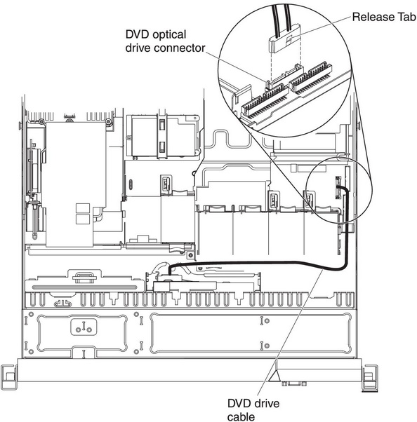
- Connect the DVD drive cable (see Installing the DVD cable). The following illustration shows the cable routing for the DVD drive:NoteThe DVD cable should go on the top of the operation information panel cable (in the middle) and the Video/USB cable (on the bottom) when all three cables are installed in the server.Figure 4. DVD drive cable connection
Give feedback