Installing a microprocessor and heat sink
Use this information to install a microprocessor and heat sink.
The following notes describe the type of microprocessor that the server supports and other information that you must consider when you install a microprocessor and heat sink:
- Microprocessors are to be installed only by trained service technicians.ImportantAlways use the microprocessor installation tool to remove a microprocessor. Failing to use the microprocessor installation tool may damage the microprocessor sockets on the system board. Any damage to the microprocessor sockets may require replacing the system board.
- The server supports up to two IntelXeon multi-core microprocessors. See Lenovo ServerProven website for a list of supported microprocessors.
- Do not install an Intel Xeon™ 5500 series microprocessor and an Intel Xeon™ 5600 series microprocessor in the same server.
- Do not mix dual-core, quad-core, and six-core microprocessors in the same server.
- The first microprocessor must always be installed in microprocessor socket 1 on the system board.
- When one microprocessor is installed, a heat sink filler is not required for microprocessor socket 2, however, the microprocessor 2 air baffle and the DIMM air baffle must be installed to provide proper system cooling.
- Do not remove the first microprocessor from the system board when you install the second microprocessor.
- When you install the second microprocessor, you must also install additional memory and the sixth fan. See Installing a memory module for details about the installation sequence.
- To ensure proper server operation when you install an additional microprocessor, use microprocessors that have the same QuickPath Interconnect (QPI) link speed, integrated memory controller frequency, core frequency, power segment, internal cache size, and type.
- Mixing microprocessors of different stepping levels within the same server model is supported.
- When mixing microprocessors with different stepping levels within the same server model, you do not have to install the microprocessor with lowest stepping level and features in microprocessor socket 1.
- Both microprocessor voltage regulator modules are integrated on the system board.
- If you have to replace a microprocessor, call for service.
- Read the documentation that comes with the microprocessor, so that you can determine whether you have to update the server firmware. To download the latest level of server firmware and other code updates for your server, go to Lenovo Data Center Support.
- The microprocessor speeds are automatically set for this server; therefore, you do not have to set any microprocessor frequency-selection jumpers or switches.
- If the thermal-grease protective cover (for example, a plastic cap or tape liner) is removed from the heat sink, do not touch the thermal grease on the bottom of the heat sink or set down the heat sink. For more information about applying or working with thermal grease, see Thermal grease.NoteRemoving the heat sink from the microprocessor destroys the even distribution of the thermal grease and requires replacing the thermal grease.
- To order an additional optional microprocessor, contact your IBM marketing representative or authorized reseller.
To install an additional microprocessor and heat sink, complete the following steps:
Attention
When you handle static-sensitive devices, take precautions to avoid damage from static electricity. For details about handling these devices, see Handling static-sensitive devices.
- Read the safety information that begins on Safety and Installation guidelines.
- Turn off the server and peripheral devices and disconnect the power cords and all external cables.
- Remove the cover (see Removing the cover).
- Install the microprocessor:
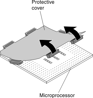
- If there is a plastic protective cover on the bottom of the microprocessor, carefully remove it.Figure 1. Protective cover removal
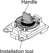
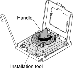
- Twist the handle of the installation tool counterclockwise so that it is in the open position.Figure 2. Installation tool handle adjustment
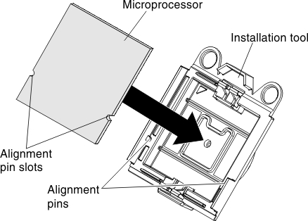
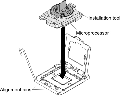
- Align the microprocessor alignment slots with the alignment pins on the microprocessor installation tool and place the microprocessor on the underside of the tool so that the tool can grasp the microprocessor correctly.Figure 3. Microprocessor alignment
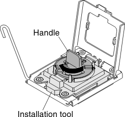
- Twist the handle of the installation tool clockwise to secure the microprocessor in the tool.NoteYou can pick up or release the microprocessor by twisting the microprocessor installation tool handle.Figure 4. Installation tool handle adjustment
- Carefully align the microprocessor installation tool over the microprocessor socket. AttentionThe microprocessor fits only one way on the socket. You must place a microprocessor straight down on the socket to avoid damaging the pins on the socket. The pins on the socket are fragile. Any damage to the pins may require replacing the system board.Figure 5. Microprocessor installation
- Twist the handle on the microprocessor tool counterclockwise to insert the microprocessor into the socket.Figure 6. Installation tool handle adjustment
- If there is a plastic protective cover on the bottom of the microprocessor, carefully remove it.
- Install the heat sink:
- Lower the rear flange of the heat sink into the opening in the retainer bracket and press down firmly on the front of the heat sink until it is seated securely.Figure 7. Heat sink installation
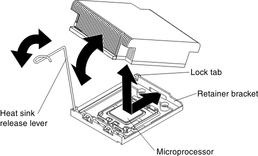
- Lower the rear flange of the heat sink into the opening in the retainer bracket and press down firmly on the front of the heat sink until it is seated securely.
- If you installed the second microprocessor, install the sixth fan (see Installing a hot-swap fan assembly).
- If you removed the microprocessor 2 air baffle, install it (see Installing the microprocessor 2 air baffle).
Give feedback