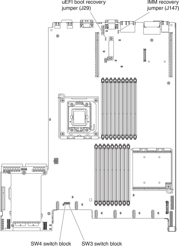
System-board switches and jumpers
The following illustration shows the location and description of the switches and jumpers.
Note
If there is a clear protective sticker on the top of the switch blocks, you must remove and discard it to access the switches.
Figure 1. System-board switches and jumpers
| Jumper number | Jumper name | Jumper setting |
|---|---|---|
| J29 | UEFI boot recovery jumper |
|
| J147 | IMM recovery jumper |
|
Table notes
| ||
The following table describes the functions of the SW3 switch block on the system board.
| Switch number | Default position | Description |
|---|---|---|
| 1 | Off | Clear CMOS memory. When this switch is toggled to On, it clears the data in CMOS memory. |
| 2 | Off | Trust Platform Module (TPM) physical presence. Turning this switch to the on position indicates a physical presence to the TPM. |
| 3 | Off | Reserved. |
| 4 | Off | Reserved. |
The following table describes the functions of the SW4 switch block on the system board.
| Switch number | Default position | Description |
|---|---|---|
| 1 | Off | Power-on password override. Changing the position of this switch bypasses the power-on password check the next time the server is turned on and starts the Setup utility so that you can change or delete the power-on password. You do not have to move the switch back to the default position after the power-on password in overridden. Changing the position of this switch does not affect the administrator password check if an administrator password is set. See Passwords for additional information about passwords. |
| 2 | Off | When you toggle this switch On and then Off, you force a power-on, which overrides the power-on and power-off button on the server and they become nonfunctional. |
| 3 | Off | (Trained service technician only) Forced power permission. Changing the position of this switch overrides the IMM power-on checking process. |
| 4 | Off | Reserved. |
Important
- Before you change any switch settings or move any jumpers, turn off the server; then, disconnect all power cords and external cables. Review the information in Safety, Installation guidelines, Handling static-sensitive devices, and Turning off the server.
- Any system-board switch or jumper blocks that are not shown in the illustrations in this document are reserved.
Give feedback