Light path diagnostics
Light path diagnostics is a system of LEDs on various external and internal components of the server. When an error occurs, LEDs are lit throughout the server. By viewing the LEDs in a particular order, you can often identify the source of the error.
When LEDs are lit to indicate an error, they remain lit when the server is turned off, provided that the server is still connected to power and the power supply is operating correctly.
Before you work inside the server to view light path diagnostics LEDs, read the safety information that begins on Safety and Handling static-sensitive devices.
If an error occurs, view the light path diagnostics LEDs in the following order:
- Look at the operator information panel on the front of the server.
- If the information LED is lit, it indicates that information about a suboptimal condition in the server is available in the IMM system-event log or in the system-error log.
- If the system-error LED is lit, it indicates that an error has occurred; go to Step 2.
The following illustration shows the operator information panel:Figure 1. Operator information panel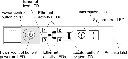
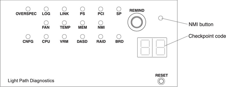
- To view the light path diagnostics panel, slide the blue release latch on the operator panel to the left. Pull forward on the panel until the hinge of the operator panel is free of the server chassis. Then pull down on the panel so that you can view the light path diagnostics panel information. This reveals the light path diagnostics panel. Lit LEDs on this panel indicate the type of error that has occurred. NoteWhen you slide the light path diagnostics panel out of the server to check the LEDs or checkpoint codes, do not run the server continuously with the light path diagnostics panel outside of the server. The panel should only be outside of the server a short time. The light path diagnostics panel must remain in the server when the server is running to ensure proper cooling.The following illustration shows the light path diagnostics panel:Figure 2. Light path diagnostics panel exposure
Note any LEDs that are lit, and then reinstall the light path diagnostics panel in the server.
NoteWhen you slide the light path diagnostics panel out of the server to check the LEDs or checkpoint codes, do not run the server continuously with the light path diagnostics panel outside of the server. The panel should only be outside of the server a short time. The light path diagnostics panel must remain in the server when the server is running to ensure proper cooling.Look at the system service label inside the server cover, which gives an overview of internal components that correspond to the LEDs on the light path diagnostics panel. This information and the information in Light path diagnostics LEDs can often provide enough information to diagnose the error.
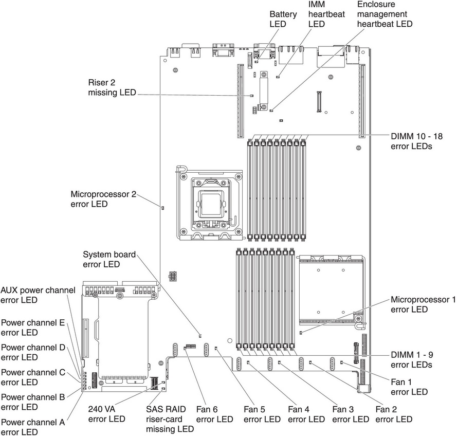
- Remove the server cover and look inside the server for lit LEDs. Certain components inside the server have LEDs that are lit to indicate the location of a problem.The following illustration shows the LEDs and connectors on the system board.Figure 3. System-board LEDs
- Remind button: Press this button to place the system-error LED on the front information panel into Remind mode. By placing the system-error LED indicator in Remind mode, you acknowledge that you are aware of the last failure but will not take immediate action to correct the problem. In Remind mode, the system-error LED flashes rapidly until one of the following conditions occurs:
- All known errors are corrected.
- The server is restarted.
- A new error occurs, causing the system-error LED to be lit again.
- NMI button: The NMI button on the front panel will come on when this button is pressed. Press this button to force a nonmaskable interrupt to the microprocessor. You might have to use a pen or the end of a straightened paper clip to press the button. It allows you to blue screen the server and take a memory dump (use this button only when directed by the IBM service support).
- Checkpoint code display: This display provides a checkpoint code that indicates the point at which the system stopped during the boot block and POST. A checkpoint code is either a byte or a word value that is produced by UEFI. The display does not provide error codes or suggest components to be replaced.
- Reset button: Press this button to reset the server and run the power-on self-test (POST). You might have to use a pen or the end of a straightened paper clip to press the button. The Reset button is in the lower-right corner of the light path diagnostics panel.