Internal cable routing and connectors
Use this information to view the cable connection and connectors.
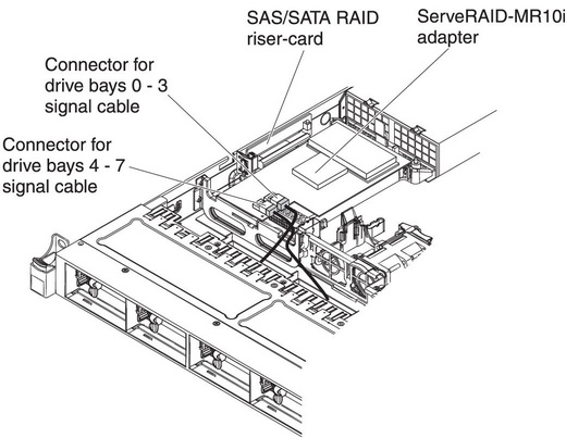
The following illustration shows the internal routing and connectors for the two SAS signal cables (in server models with eight drive bays).
- To connect the SAS signal cables, make sure that you first connect the signal cable, and then the power cable and configuration cable.
- To disconnect the SAS signal cables, make sure that you first disconnect the power cable, and then the signal cable and configuration cable.
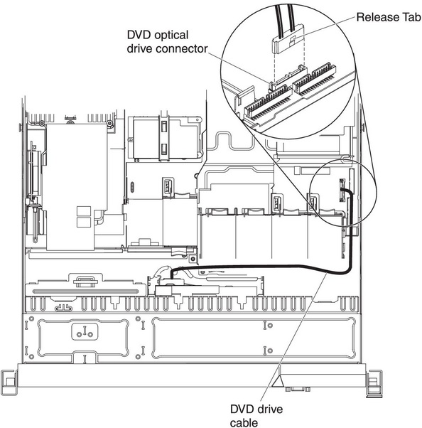
The following illustration shows the internal routing and connector for the optional optical drive cable.
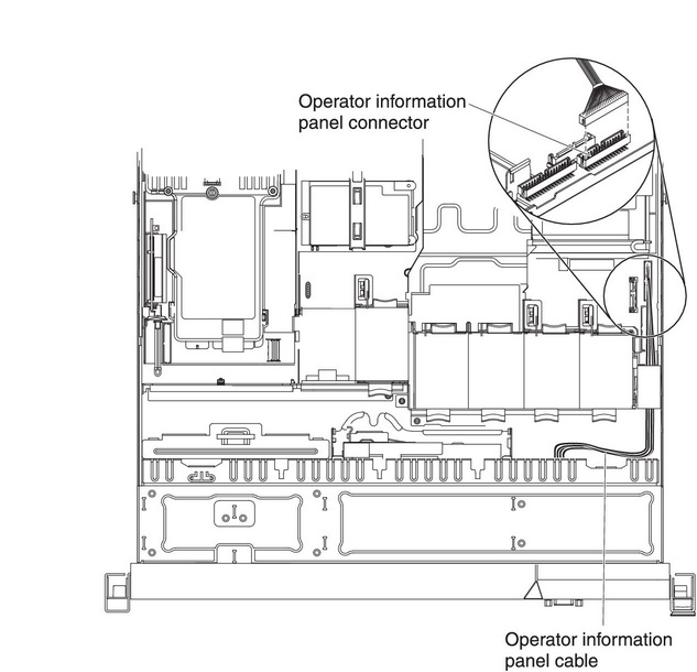
The following illustration shows the internal routing and connector for the operator information panel cable. The following notes describe additional information you must consider when you install or remove the operator information panel cable:
- You may remove the optional optical drive cable to obtain more room before you install or remove the operator information panel cable.
- To remove the operator information panel cable, slightly press the cable toward the chassis; then, pull to remove the cable from the connector on the system board. Pulling the cable out of the connector by excessive force might cause damage to the cable or connector.
- To connect the operator information panel cable on the system board, press evenly on the cable. Pressing on one side of the cable might cause damage to the cable or connector.AttentionFailing to install or remove the cable with care may damage the connectors on the system board. Any damage to the connectors may require replacing the system board.
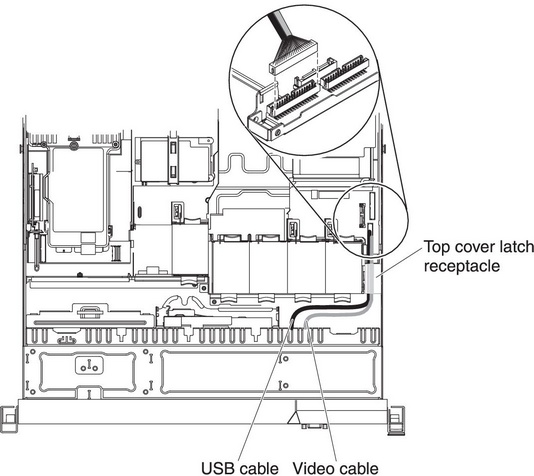
The following illustration shows the internal routing and connector for the USB/video cable. The following notes describes other information you must consider when you install or remove the USB/video cable:
- You may remove the optional optical drive cable to obtain more room before you install or remove the operator information panel cable.
- The USB/video cable is routed under the video cable and then both the USB and video cables are routed under the cable retention tab and the top cover latch receptacle.
- To remove the USB/video cable, slightly press the cable toward the chassis; then, pull to remove the cable from the connector on the system board. Pulling the cable out of the connector by excessive force might cause damage to the cable or connector.
- To connect the USB/video cable on the system board, press evenly on the cable. Pressing on one side of the cable might cause damage to the cable or connector.
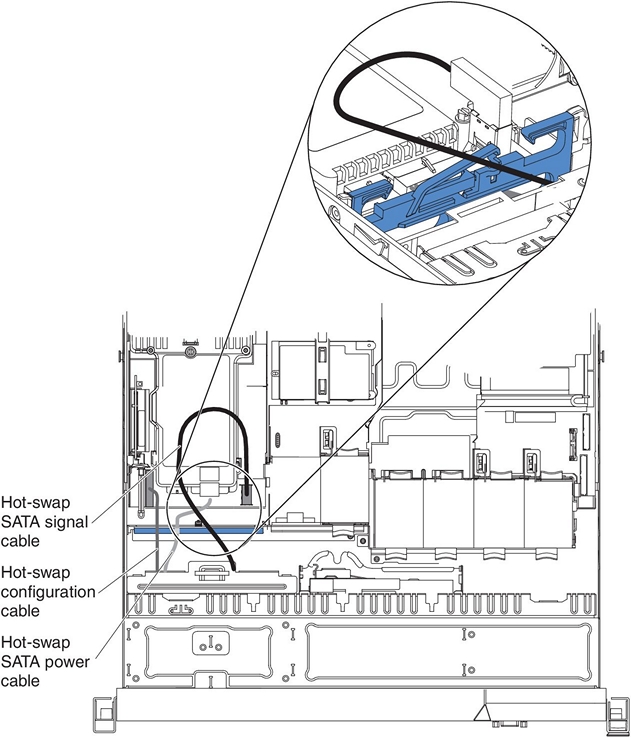
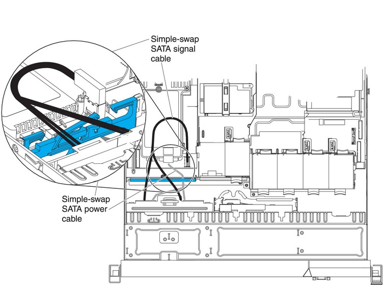
The following illustration shows the internal routing for the SATA power cable and signal cable.
The following illustration shows the internal routing for the SATA power cable, the SATA signal cable, and the configuration cable.