Installing a SAS/SATA 8 Pac HDD option
Use this information to install a SAS/SATA 8 Pac HDD option.
You can install a Lenovo System x3650 M4 Hot-swap SAS/SATA 8 Pac HDD option to add eight additional 2.5-inch hot-swap hard disk drives in the server. See the Lenovo ServerProven website for a list of supported optional devices. To order a SAS/SATA 8 Pac HDD option, contact your sales representative or reseller.
The SAS/SATA 8 Pac HDD option kit contains the following components:
- One 2.5-inch hard disk drive backplane
- One SAS expander adapter
- Two M3 x 5 screws
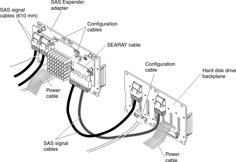
- One SEARAY cable, which contains two SAS signal cables attached to the expander adapter
- Two SAS signal cables (610 mm)
Note
The 8 pac HDD option including structural parts and Tier 1 parts.
To install a SAS/SATA 8 Pac HDD option, complete the following steps:
- Remove the two 4-drive filler panels that are to the right of drive bay 8, beneath the IDs 8 - 15 on the front bezel.Figure 1. Filler panels

- Remove hard disk drive backplane 1 from the server.Figure 2. Hard disk drive backplane removal

- Install the new backplane in slot 2:
- Screw the SEARAY cable to backplane 2 as shown in the following illustration and connect two SAS signal cables to backplane 1.Figure 3. Cables connection
- Angle the new backplane and place the bottom edge into the slots for backplane 2 on the chassis next to the optical drive.Figure 4. New backplane installation

- Screw the SEARAY cable to backplane 2 as shown in the following illustration and connect two SAS signal cables to backplane 1.
- Connect the loose end of the SAS signal cables (610 mm) to the system board. Route the cable underneath the cable retention features on the baffle. See the illustration.Figure 5. SAS signal cables (610 mm) routing

- Make sure that the configuration cable is connected to the backplanes and system board.Figure 6. Configuration cable routing

- Make sure that the SAS power cable is connected to the backplanes and system board.Figure 7. SAS power cable routing

If you have other devices to install or remove, do so now. Otherwise, go to Completing the installation.
Give feedback