Removing the system board
Use this information to remove the system board.
Note
- When you replace the system board, you must either update the server with the latest firmware or restore the pre-existing firmware that the customer provides on a diskette or CD image. Make sure that you have the latest firmware or a copy of the pre-existing firmware before you proceed.
- Before you replace the system board, make sure that you back up any features on demand (FoD) keys that were enabled. Reactivate any Features on Demand features. Instructions for automating the activation of features and installing activation keys is in the Features on Demand User's Guide. To download the document, go to Lenovo Features on Demand website, log in, and click .
To remove the system board, complete the following steps:
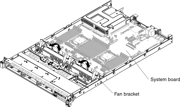
- Rotate the fan assembly bracket up toward the front of the server.Figure 1. Fan assembly bracket rotation
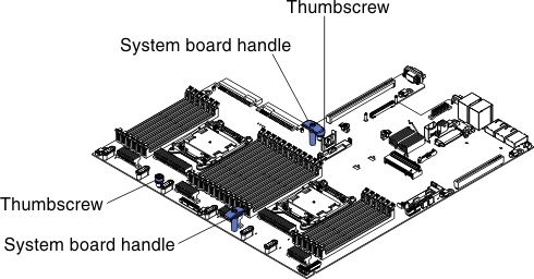
- Loosen the two thumbscrews (one is near PCI slot 2 and one is between fans 4 and 5). Figure 2. Thumbscrews disengagement
- Grasp the system board handles and slide the system board toward the front of the server until it stops.Figure 3. System-board standoffs
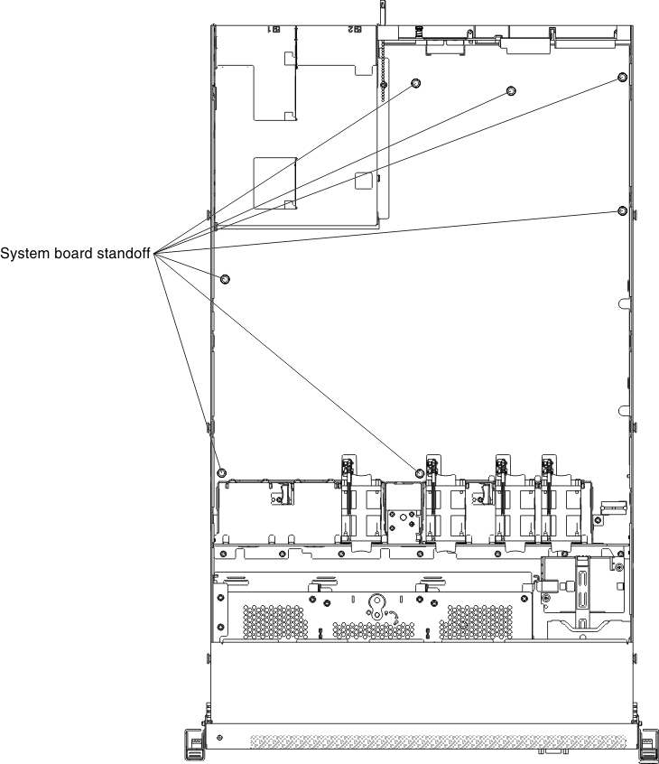 NoteMake sure that the system board disengage from all system-board standoffs.
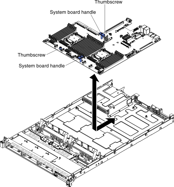
 - Grasp the system board handles and lift up the system board and carefully remove it from the server, being careful not to damage any surrounding components.Figure 4. System board removal
Give feedback