Removing a microprocessor and heat sink
Use this information to remove a microprocessor and heat sink.
- Microprocessors are to be removed only by trained technicians.ImportantAlways use the microprocessor installation tool to remove a microprocessor. Failing to use the microprocessor installation tool may damage the microprocessor sockets on the system board. Any damage to the microprocessor sockets may require replacing the system board.
- Be extremely careful, the microprocessor socket contacts are very fragile. Do not touch the microprocessor socket contacts. Contaminants on the microprocessor contacts or microprocessor socket contacts, such as oil from your skin, can cause connection failures between the contacts and the socket.
- Do not allow the thermal grease on the microprocessor and heat sink to come in contact with anything. Contact with any surface can contaminate the thermal grease and the microprocessor socket.
- Do not use any tools or sharp objects to lift the locking levers on the microprocessor socket. Doing so might result in permanent damage to the system board.
- Each microprocessor socket must always contain either a socket cover or a microprocessor and heat sink.
- Be sure to use only the installation tools provided with the new microprocessor to remove or install the microprocessor. Do not use any other tool.
- When installing multiple microprocessors, open one microprocessor socket at a time to avoid damaging other microprocessor socket contacts.
- The microprocessor installation tool has the microprocessor installed on the tool, and may have a protective cover over the microprocessor. Do not use the tool, or remove the cover until you are instructed to do so.
Note
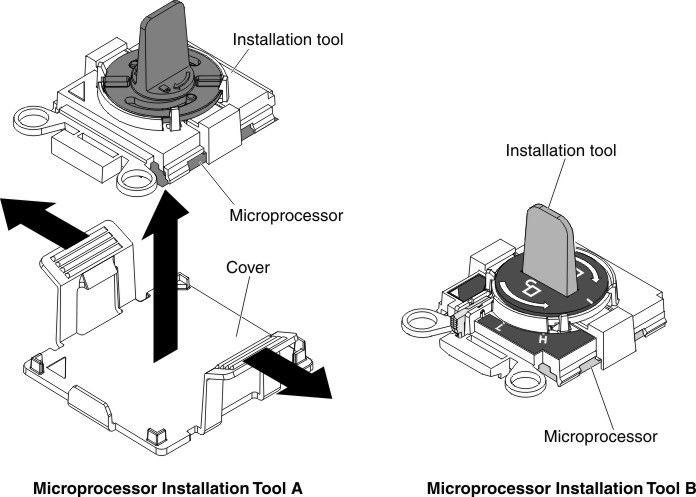
Be sure to use the installation tool that comes with your microprocessor installation tool assembly. The tools are similar in function and design, however Tool A has one setting for installing one size of microprocessor, and supports the following families of microprocessors: E5-26xx, E5-46xx. Installation Tool B has two settings for installing two different sizes of microprocessors. The settings that are marked on Tool B are
Lfor smaller low core microprocessors, and
Hfor larger high core microprocessors. Installation Tool B supports the following families of microprocessors: E5-26xx, E5-46xx, E5-26xx v2, E5-46xx v2.
Microprocessor Installation Tools A and B are shown in the following illustration.
Figure 1. Microprocessor installation tools
To remove a microprocessor and heat sink, complete the following steps:
- Remove the heat sink. AttentionDo not touch the thermal material on the bottom of the heat sink. Touching the thermal material will contaminate it. If the thermal material on the microprocessor or heat sink becomes contaminated, you must wipe off the contaminated thermal material on the microprocessor or heat sink with the alcohol wipes and reapply clean thermal grease to the heat sink.
- Lift the heat sink out of the server. After removal, place the heat sink (with the thermal grease side up) on a clean, flat surface.Figure 2. Heat sink removal
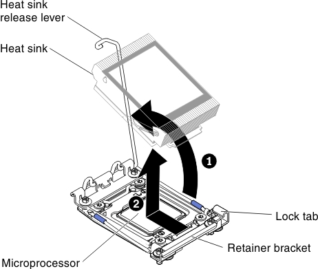
- Lift the heat sink out of the server. After removal, place the heat sink (with the thermal grease side up) on a clean, flat surface.
- Open the microprocessor socket release levers and retainer.Figure 3. Microprocessor socket levers and retainer disengagement
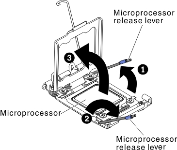
- Remove the microprocessor from the socket.
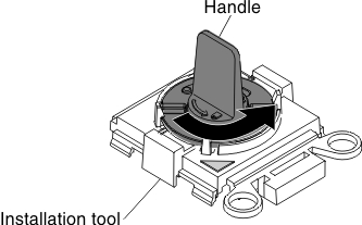
- Select the empty installation tool and ensure that the handle is in the open position. If the installation tool handle is not in the open position, use the following instructions for your installation tool:
- If using Installation Tool A, twist the microprocessor installation tool handle counterclockwise to the open position.Figure 4. Installation tool handle adjustment
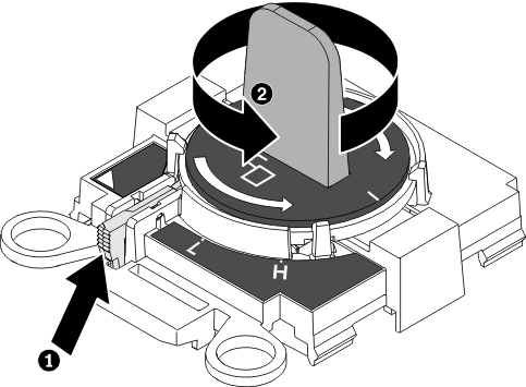
- If using Installation Tool B, 1 lift the interlock latch and hold it up while you 2 twist the microprocessor installation tool handle counterclockwise to the open position, and then release the interlock latch. The following illustration of the installation tool shows the location of the interlock latch and counterclockwise rotation of the handle before loading the microprocessor.Figure 5. Installation tool handle adjustment
- If using Installation Tool A, twist the microprocessor installation tool handle counterclockwise to the open position.
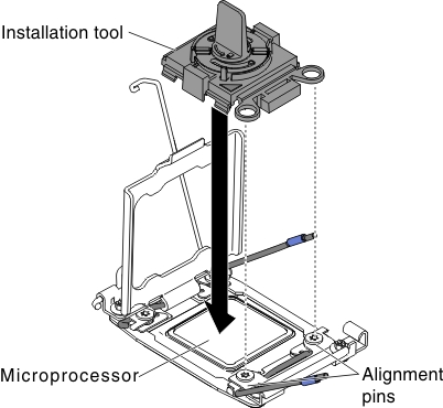
- Align the installation tool with the screws, as shown in the following graphic, and lower the installation tool on the microprocessor. The installation tool rests flush on the socket only when it is aligned correctly.Figure 6. Installation tool alignment
- Using the following instructions for your installation tool to remove the microprocessor.
- If using Installation Tool A, gently twist the handle clockwise to the closed position and lift the microprocessor out of the socket.
- If using Installation Tool B, gently twist the handle of the installation tool clockwise until it locks in the
H
orL
position, depending on the size of microprocessor, and then lift the microprocessor out of the socket.
Figure 7. Installation tool handle adjustment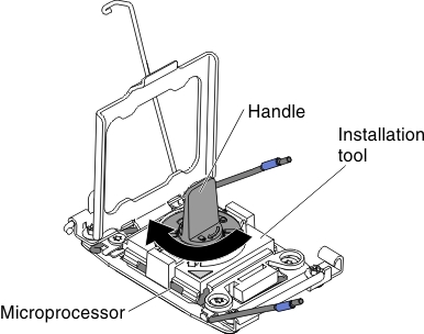
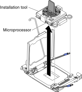
- Lift the microprocessor out of the socket.Figure 8. Installation tool removal
- Select the empty installation tool and ensure that the handle is in the open position. If the installation tool handle is not in the open position, use the following instructions for your installation tool:
If you are instructed to return the microprocessor, follow all packaging instructions, and use any packaging materials for shipping that are supplied to you.
Give feedback