Memory rank sparing
The memory rank sparing feature disables the failed memory from the system configuration and activates a rank sparing DIMM to replace the failed active DIMM.
You can enable rank sparing memory in the Setup utility, select . For more information, see Using the Setup utility.
The maximum available memory is reduced when memory rank sparing mode is enabled.
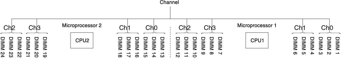
The following diagram lists the DIMM connectors on each memory channel.
Figure 1. Connectors on each memory channel
Follow the installation sequence for rank sparing mode:- Install at least one quad-rank DIMM in a channel.
- Install at least two single-rank or dual-rank DIMMs in a channel.
| Number of DIMMs | Number of installed microprocessor | DIMM connector |
|---|---|---|
| First pair of DIMMs | 1 | 1, 2 |
| Second pair of DIMMs | 1 | 4, 5 |
| Third pair of DIMMs | 1 | 8, 9 |
| Fourth pair of DIMMs | 1 | 11, 12 |
| Fifth pair of DIMMs | 1 | 7, 10 |
| Sixth pair of DIMMs | 1 | 3, 6 |
| Seventh pair of DIMMs | 2 | 13, 14 |
| Eighth pair of DIMMs | 2 | 16, 17 |
| Ninth pair of DIMMs | 2 | 20, 21 |
| Tenth pair of DIMMs | 2 | 23, 24 |
| Eleventh pair of DIMMs | 2 | 19, 22 |
| Twelfth pair of DIMMs | 2 | 15, 18 |
Table note DIMM connectors 3, 6, 7, 10, 15, 18, 19, and 22 are not used in memory rank sparing mode when UDIMMs are installed in the server. | ||
Give feedback