Replacing a hot-swap dc power supply
Use this information to install a hot-swap dc power supply.
The following notes describe the type of power supply that the server supports and other information that you must consider when you install a power supply:
- Before you install an additional power supply or replace a power supply with one of a different wattage, you may use the Power Configurator utility to determine current system power consumption. For more information and to download the utility, go to the IBM Power Configurator website.
- The server comes with one hot-swap 12-volt output power supply that connects to power supply bay 1. The input voltage is -48 V dc or -60 V dc auto-sensing.
- Before you install a dc power supply in the server, you must remove all ac power supplies. Do not use both ac and dc power supplies in the same server. Install up to two dc power supplies or up to two ac power supplies, but not a combination.
- Power supply 1 is the default/primary power supply. If power supply 1 fails, you must replace the power supply with the same wattage immediately.
- You can order an optional power supply for redundancy.
- These power supplies are designed for parallel operation. In the event of a power-supply failure, the redundant power supply continues to power the system. The server supports a maximum of two power supplies.
It is the customer's responsibility to supply the necessary power cable.
To reduce the risk of electric shock or energy hazards:- Use a circuit breaker that is rated at 25 amps.
- Use 2.5 mm2 (12 AWG) at 90° C copper wire.
- Torque the wiring-terminal screws to 0.50 ~ 0.60 newton-meters (4.43 ~ 5.31 inch-pounds).
- If the power source requires ring terminals, you must use a crimping tool to install the ring terminals to the power cord wires. The ring terminals must be UL approved and must accommodate the wire that is described in the above-mentioned note.
Statement 29:

CAUTION
This equipment is designed to permit the connection of the earthed conductor of the dc supply circuit to the earthing conductor at the equipment.
This equipment is designed to permit the connection of the earthed conductor of the dc supply circuit to the earthing conductor at the equipment. If this connection is made, all of the following conditions must be met:
- This equipment shall be connected directly to the dc supply system earthing electrode conductor or to a bonding jumper from an earthing terminal bar or bus to which the dc supply system earthing electrode conductor is connected.
- This equipment shall be located in the same immediate area (such as, adjacent cabinets) as any other equipment that has a connection between the earthed conductor of the same dc supply circuit and the earthing conductor, and also the point of earthing of the dc system. The dc system shall not be earthed elsewhere.
- The dc supply source shall be located within the same premises as this equipment.
- Switching or disconnecting devices shall not be in the earthed circuit conductor between the dc source and the point of connection of the earthing electrode conductor.
Statement 31
DANGER
danger
Electrical current from power, telephone, and communication cables is hazardous.
To avoid a shock hazard:
- Do not connect or disconnect any cables or perform installation, maintenance, or reconfiguration of this product during an electrical storm.
- Connect all power cords to a properly wired and grounded power source.
- Connect to properly wired power sources any equipment that will be attached to this product.
- When possible, use one hand only to connect or disconnect signal cables.
- Never turn on any equipment when there is evidence of fire, water, or structural damage.
- Disconnect the attached ac power cords, dc power sources, network connections, telecommunications systems, and serial cables before you open the device covers, unless you are instructed otherwise in the installation and configuration procedures.
- Connect and disconnect cables as described in the following table when you install, move, or open covers on this product or attached devices.
| To Connect: | To Disconnect: |
|---|---|
|
|
Statement 33
CAUTION
This product does not provide a power-control button. Turning off blades or removing power modules and I/O modules does not turn off electrical current to the product. The product also might have more than one power cord. To remove all electrical current from the product, make sure that all power cords are disconnected from the power source.
Statement 34
CAUTION
To reduce the risk of electric shock or energy hazards:
- This equipment must be installed by trained service personnel in a restricted-access location, as defined by the NEC and IEC 60950-1, First Edition, The Standard for Safety of Information Technology Equipment.
- Connect the equipment to a properly grounded safety extra low voltage (SELV) source. A SELV source is a secondary circuit that is designed so that normal and single fault conditions do not cause the voltages to exceed a safe level (60 V direct current).
- Incorporate a readily available approved and rated disconnect device in the field wiring.
- See the specifications in the product documentation for the required circuit-breaker rating for branch circuit overcurrent protection.
- Use copper wire conductors only. See the specifications in the product documentation for the required wire size.
- See the specifications in the product documentation for the required torque values for the wiring-terminal screws.
Important
Be sure to read the multilingual safety instructions on the CD that comes with the server before you use the product.
To install a hot-swap dc power supply, complete the following steps:
Attention
Only trained service personnel other than Lenovo service technicians are authorized to install and remove the -48 volt dc power supply, and make the connections to and disconnections from the -48 volt dc power source. Lenovo service technicians are not certified or authorized to install or remove the -48 volt power cable. The customer is responsible for ensuring that only trained service personnel install or remove the -48 volt power cable.
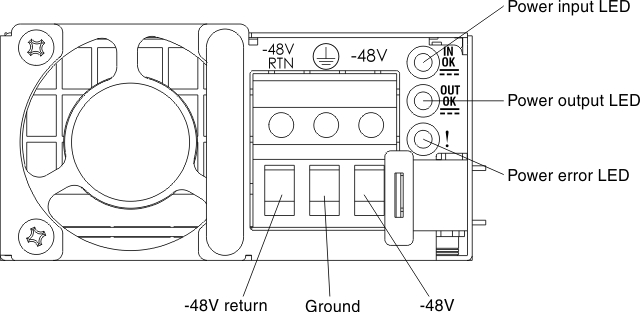
- Attach the dc power cable to the new power supply. Make sure the wires are connected securely to the -48V, ground, and -48V return terminals.Figure 1. DC power supply rear view
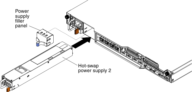
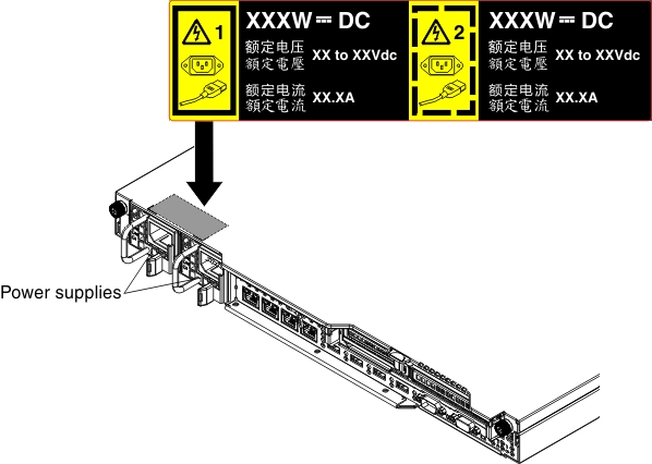
- If you are installing a hot-swap power supply into an empty bay, remove the power-supply filler from the power-supply bay. Figure 2. Power supply installation
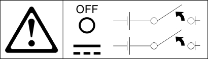
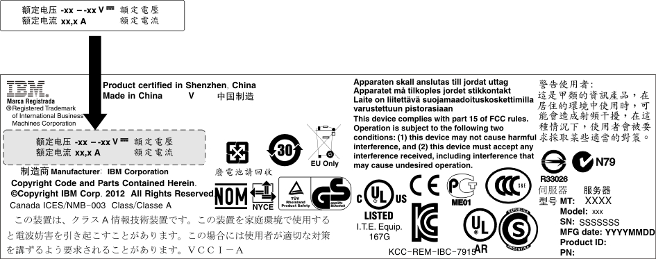
- If you are replacing a power supply with one of a different wattage in the server, apply the new power information label provided over the existing power information label on the server. Power supplies in the server must be with the same power rating or wattage to ensure that the server will operate correctly.Figure 3. Power information label
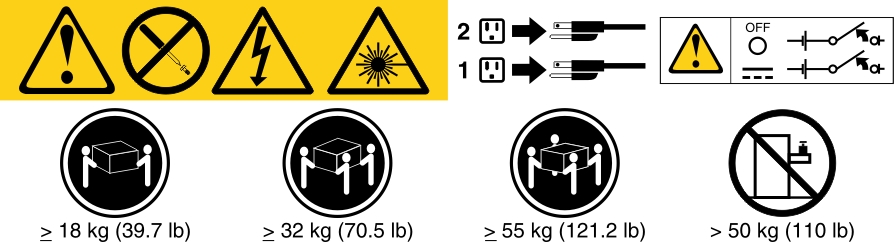
- If you are adding a power supply to the server, attach the redundant power information label that comes with this option on the server cover near the power supplies. Figure 4. Redundant power information label
Give feedback