Removing the system board
Use this information to remove the system board.
Note
- Before you replace the system board, make sure that you backup any features on demand (FoD) keys that were enabled. Remember to re-enable the features on demand (FoD) keys after installing the new system board. For more information on Features on Demand (FoD), including instructions for automating the activation and installation of the activation key by using ToolsCenter or Systems Director, see the Features on Demand User's Guide at the Lenovo Features on Demand website under the Help section.
- When you replace the system board, you must either update the server with the latest firmware or restore the pre-existing firmware from a diskette or CD image. Make sure that you have the latest firmware or a copy of the pre-existing firmware before you proceed.
Before you remove the system board from the server, take the following steps to save data, firmware, and configuration data:
- Record all system configuration information, such as IMM IP addresses, vital product data, and the machine type, model number, serial number, Universally Unique Identifier, and asset tag of the server.
- Using the Advanced Settings Utility (ASU), save the system configuration to external media.
- Save the system-event log to external media.
Note
When you replace the system board, you must either update the server with the latest firmware or restore the pre-existing firmware that the customer provides on a diskette or CD image. Make sure that you have the latest firmware or a copy of the pre-existing firmware before you proceed.
To remove the system board, complete the following steps:
- Remove all heat sinks and microprocessors, and set them aside on a static-protective surface for reinstallation (see Removing a microprocessor and heat sink).Note
- Be sure to keep the heat sink and microprocessor from each microprocessor socket of the old system board together so that you can install them on the new system board together. For example, when you remove the heat sink and microprocessor from microprocessor socket 1 of the old system board , install them both on the same socket on the new system board.
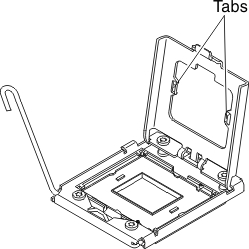
- Use an alcohol wipe to remove any thermal grease from the tabs on the microprocessor bracket frame on the old system board.Figure 1. Use an alcohol wipe to remove any thermal grease from the tabs
- Always use microprocessor installation tool to remove a microprocessor. Failing to use microprocessor installation tool may damage the microprocessor sockets on the system board. Any damage to the microprocessor sockets may require replacing the system board.
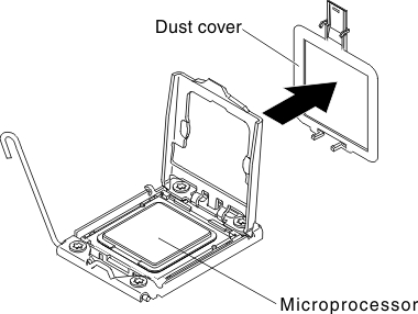
- Remove the socket covers from the microprocessor sockets on the new system board and place them on the microprocessor sockets of the old system board that you are removing.Figure 2. Socket cover removal
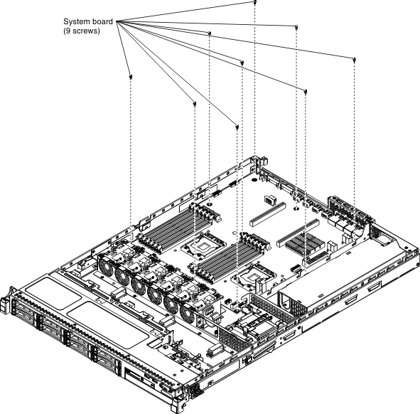
- Loosen the nine screws that secure the system board to the chassis. Figure 3. Loosen screws
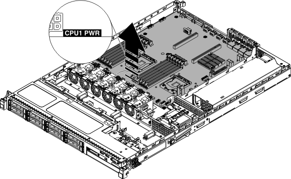
- Slightly lift the system board at the side that is near the CPU1_PWR to create a small angle of elevation between the system board and chassis.Figure 4. Tilt the system board
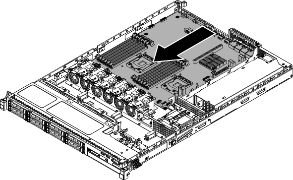
- Gently push the external input/output connectors toward to the fan cage as much as possible.Figure 5. Push the system board toward to the fan cage
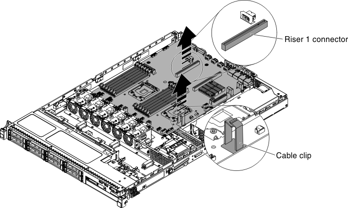
- Grasp the system board on both the cable clip near the microprocessor 2 and PCI riser card connector 1. Then, slightly lift the system board to create a small angle of elevation by leaning the edge against the partition of the power supply between the system board and chassis.Figure 6. Lift the system board slightly
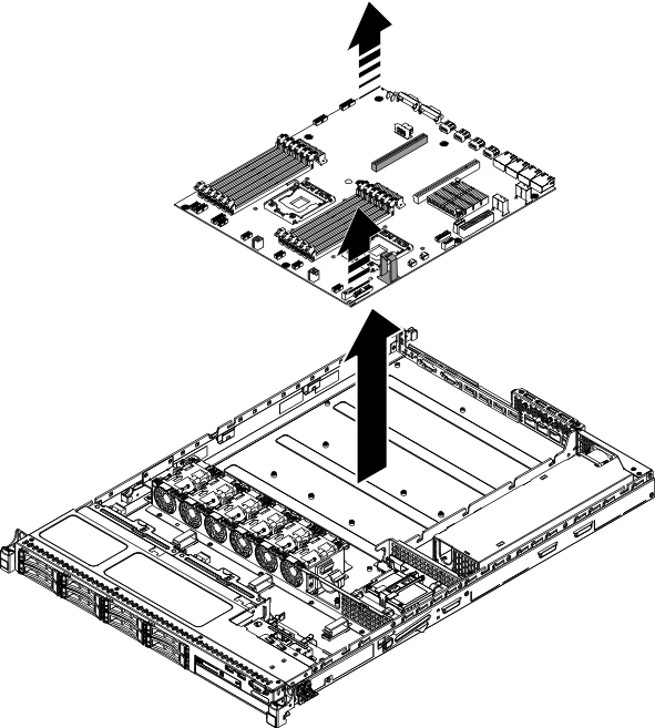
- Carefully lift up the system board by placing both hands diagonally and remove it from the chassis. Be careful to avoid damage any surrounding components or bend the pin inside the microprocessor socket.Figure 7. System board removal
Give feedback