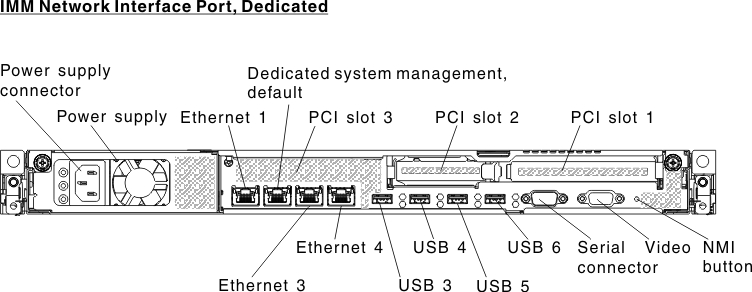
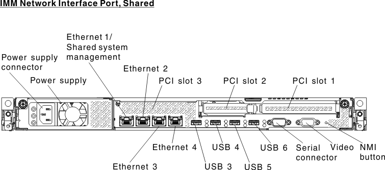
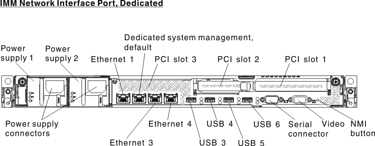
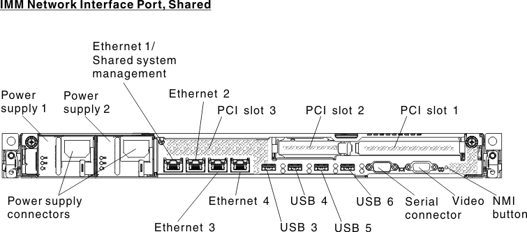
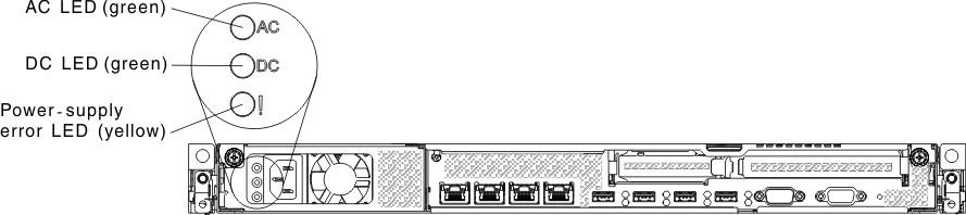
Rear view
The following illustrations show the connectors and LEDs on the rear of the server.
The following illustrations show the connectors on the rear of the server.
Figure 1. Rear view of server
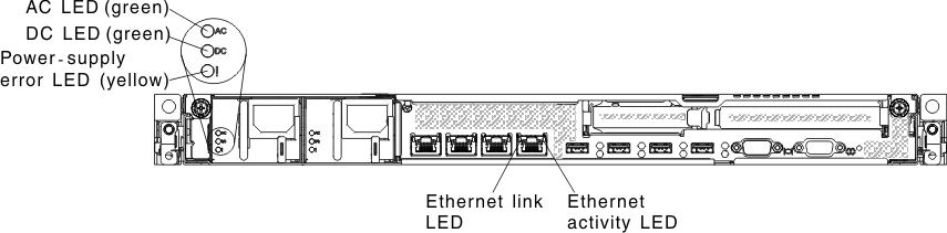
The following illustrations show the locations of the power-supply LEDs for fixed and redundant models respectively on the rear of the server.
Figure 2. The LEDs on the rear of the server
- PCI riser slot 1: Insert a full-height, half-length PCI Express adapter into this slot. See Installing an adapter for the supported adapters for these riser-cards.
- PCI riser slot 2: Insert a low-profile PCI Express adapter into this slot. See Installing an adapter for information about adapters that this riser card support.
- Power connector: Connect the power cord to this connector.
- AC power LED: Each power supply has an ac power LED and a dc power LED. When the ac power LED is lit, it indicates that sufficient power is being supplied to the power supply through the power cord. During normal operation, both the ac and dc power LEDs are lit. For any other combination of LEDs, see Power-supply LEDs.
- DC power LED: Each power supply has a dc power LED and an ac power LED. When the dc power LED is lit, it indicates that the power supply is supplying adequate dc power to the system. During normal operation, both the ac and dc power LEDs are lit. For any other combination of LEDs, see Power-supply LEDs.
- Power-supply error LED: Each power supply has an ac power LED and a dc power LED. When the power-supply error LED is lit, it indicates that the power supply has failed.
- Video connector: Connect a monitor to this connector. The video connectors on the front and rear of the server can be used simultaneously.NoteThe maximum video resolution is 1600 x 1200 at 75 Hz.
- Serial connector: Connect a 9-pin serial device to this connector. The serial port is shared with the integrated management moduleII (IMM2). The IMM2 can take control of the shared serial port to redirect serial traffic, using Serial over LAN (SOL).
- USB connectors: Connect a USB device to any of these connectors.
- Ethernet activity LEDs: When these LEDs are lit, they indicate that the server is transmitting to or receiving signals from the Ethernet LAN that is connected to the Ethernet port.
- Ethernet link LEDs: When these LEDs are lit, they indicate that there is an active link connection on the 10BASE-T, 100BASE-TX, or 1000BASE-TX interface for the Ethernet port.
- Ethernet and system-management connectors:
- IMM2 dedicated mode (default): In this mode, which is the default setting for the server, the Ethernet 2 connector connects to a network for full systems-management information control. A dedicated management network provides additional security by physically separating the management network traffic from the production network. Meanwhile, the Ethernet 1, Ethernet 3 and Ethernet 4 connectors are used to connect to the production network. See Using the Setup utility for more information.
- IMM2 shared mode: In this mode, the Ethernet 1 connector is used to connect to a network for full systems-management information control and production network. See Using the Setup utility for more information.
NoteThe IMM2 network must operate at 100 Mbps full duplex. The IMM2 network connection does not support Gigabit Ethernet. However, in shared mode the production Ethernet network still operates at Gigabit speeds.Table 1. UEFI settings for remote access to the IMM UEFI mode Ethernet Port 1 Ethernet Port 2 Ethernet Port 3 (optional) Ethernet Port 4 (optional) IMM network interface port dedicated (default) Production Ethernet IMM2 dedicated (please see note) Production Ethernet Production Ethernet IMM network interface port shared Shared - Production Gb Ethernet and IMM2 (please see note) Production Ethernet Production Ethernet Production Ethernet NoteThe IMM network is limited to 100 Mbps full duplex.
Give feedback