Light path diagnostics
Light path diagnostics is a system of LEDs on various external and internal components of the server that leads you to the failed component. When an error occurs, LEDs are lit along the path of the front panel, the light path diagnostics panel, then on the failed component. By viewing the LEDs in a particular order, you can often identify the source of the error.
When LEDs are lit to indicate an error, they remain lit when the server is turned off, provided that the server is still connected to power and the power supply is operating correctly and the top cover is closed and latched correctly.
Before you work inside the server to view light path diagnostics LEDs, read the safety information that begins in Safety and Handling static-sensitive devices.
If an error occurs, view the light path diagnostics LEDs in the following order:
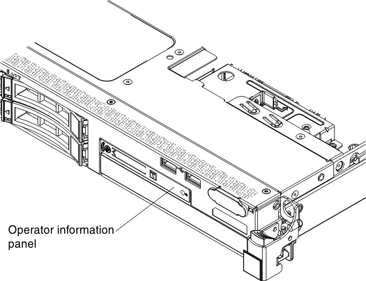
- Look at the operator information panel on the front of the server.
- If the Log LED is lit, it indicates that information about a suboptimal condition in the server is available in the IMM system-event log or in the system-event log.
- If the system-error LED is lit, it indicates that an error has occurred; go to step 2.
The following illustration shows the operator information panel:Figure 1. Operator information panel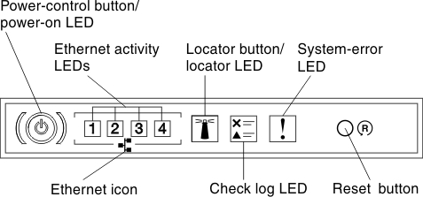
- To view the advanced operator information panel, press the blue latch on the right of the operator panel. Lit LEDs on this panel indicate the type of error that has occurred.
Look at the system service label inside the server cover, which gives an overview of internal components that correspond to the LEDs on the light path diagnostics panel. This information and the information in Light path diagnostics LEDs can often provide enough information to diagnose the error.
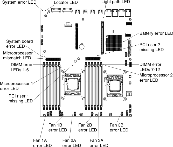
- Remove the server cover and look inside the server for lit LEDs. Certain components inside the server have LEDs that are lit to indicate the location of a problem.The following illustration shows the LEDs on the system board.Figure 2. LEDs on the system board