System-board jumpers
The following illustration shows the location and description of the switches and jumpers.
Figure 1. Location and description of switches and jumpers
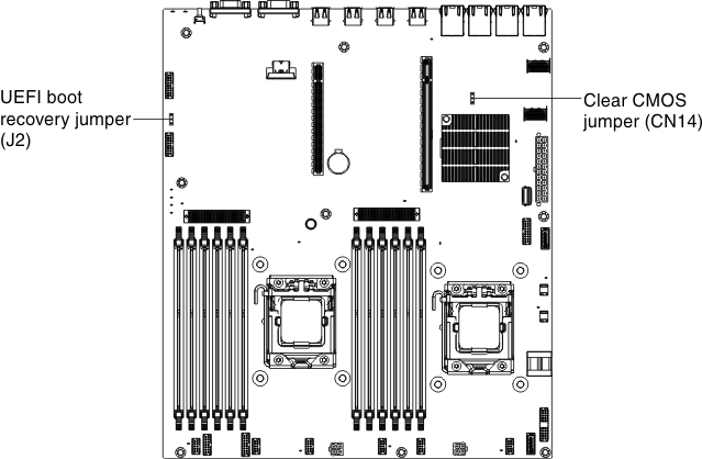
The following table describes the jumper on the system board.
| Jumper number | Jumper name | Jumper setting |
|---|---|---|
| CN14 | Clear CMOS jumper |
|
| J2 | UEFI boot recovery jumper |
|
Note
| ||
Important:
- Before you change any switch settings or move any jumpers, turn off the server; then, disconnect all power cords and external cables. Review the information in Safety, Installation guidelines, Handling static-sensitive devices, and Turning off the server.
- Any system-board switch or jumper blocks that are not shown in the illustrations in this document are reserved.
Give feedback