Installing an additional microprocessor and heat sink
The following notes describe the type of microprocessor that the server supports and other information that you must consider when you install a microprocessor and heat sink.
Note
If your server comes with one Intel Pentium 1400 series microprocessor, the second microprocessor socket is not used. The server supports only one Intel Pentium microprocessor. If you plan to install two Intel Xeon microprocessors in the server, you must first remove the Intel Pentium microprocessor that came with the server.
- A microprocessor must be replaced or serviced by a trained technician.
- Be extremely careful, the pins on the socket are fragile. Any damage to the pins may require replacing the system board.
- The microprocessor tool assembly comes with the microprocessor and microprocessor cover attached to the tool. The microprocessor comes protected between the tool and the microprocessor cover. Store the microprocessor tool in a safe location for future use.
- Use the microprocessor tool to install or remove a microprocessor in the server. Failure to use the microprocessor tool may cause damage to the pins in the socket. Any damage to the pins may require replacing the system board.
- The server supports one Intel Pentium 1400 series microprocessor or up to two IntelXeon four-core, six-core, or eight-core microprocessors (depending on your model). To confirm that the server supports the microprocessor, see the Lenovo ServerProven website for a list of supported microprocessors.
- Do not mix four-core, six-core, and eight-core microprocessors in the same server.
- The microprocessor options that Lenovo supports are limited by the capacity and capability of the server. Any microprocessor options that you install must have the same specifications as the microprocessor(s) that came with the server.
- The first microprocessor must always be installed in microprocessor socket 1 on the system board.
- Do not remove the first microprocessor from the system board when you install the second microprocessor.
- When you install the second microprocessor, you must also install additional memory and the fourth and sixth fans. See Installing a memory module for details about the memory installation sequence.
- To ensure proper server operation when you install an additional microprocessor, use microprocessors that have the same QuickPath Interconnect (QPI) link speed, integrated memory controller frequency, core frequency, power segment, internal cache size, and type.
- Mixing microprocessors of different stepping levels within the same server model is supported.
- When mixing microprocessors with different stepping levels within the same server model, you do not have to install the microprocessor with lowest stepping level and features in microprocessor socket 1.
- Both microprocessor voltage regulator modules are integrated on the system board.
- Read the documentation that comes with the microprocessor, so that you can determine whether you have to update the server firmware. To download the latest level of the server firmware and other code updates for your server, go to the Lenovo Support Portal.
- If the thermal-grease protective cover (for example, a plastic cap or tape liner) is removed from the heat sink, do not touch the thermal grease on the bottom of the heat sink or set down the heat sink. For details, see Thermal grease.NoteRemoving the heat sink from the microprocessor destroys the even distribution of the thermal grease and requires replacing the thermal grease.
- To order an additional optional microprocessor, contact your Lenovo marketing representative or authorized reseller.
- The following table shows the DIMM connectors on the system board and the DIMM connectors that are associated with each microprocessor:
Table 1. DIMM connectors associated with each microprocessor Microprocessor DIMM connectors Microprocessor socket 1 1 through 6 Microprocessor socket 2 7 through 12
To install an additional microprocessor and heat sink, complete the following steps:
- Open the microprocessor socket release lever and retainer.
- Lift the hinged microprocessor bracket frame into an open position.AttentionWhen you handle static-sensitive devices, take precautions to avoid damage from static electricity. For details about handling these devices, see
Handling static-sensitive devices. Figure 1. Lift the bracket frame into an open position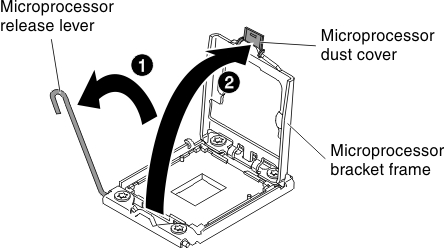
- Lift the hinged microprocessor bracket frame into an open position.
- Install the microprocessor:
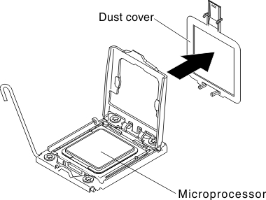
- Remove the socket cover from the microprocessor socket.Figure 2. Microprocessor Installation
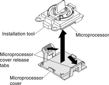
- Remove the cover from the bottom of the microprocessor installation tool. Press both microprocessor cover release tabs outward (in opposite directions as shown in the illustration) and remove the microprocessor installation tool with the microprocessor attached.Figure 3. Microprocessor removal with microprocessor installation tool
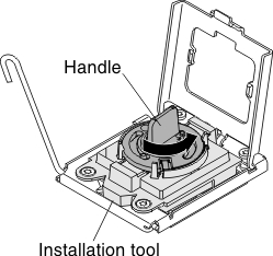
- Carefully align the microprocessor installation tool over the microprocessor socket. .NoteThe microprocessor fits only one way in the socket.Figure 4. Microprocessor installation alignment
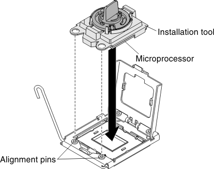
- Twist the handle on the microprocessor tool counterclockwise to insert the microprocessor into the socket.Figure 5. Microprocessor insertion
- Remove the socket cover from the microprocessor socket.
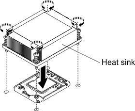
- Install the heat sink that came with the microprocessor:
- Align the screws on the heat sink with the screw holes on the system board; then, place the heat sink on the microprocessor with the thermal-grease side down. Figure 6. Heat sink placement
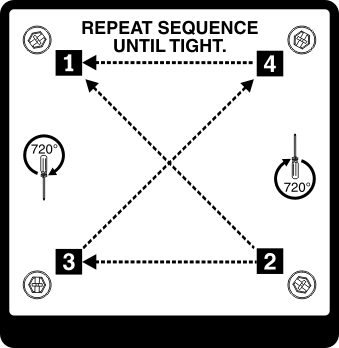
- Press firmly on the captive screws and tighten them with a screwdriver. The follow illustration shows the sequence in tightening the screws, which is also shown on top of the heat sink. Begin with the screw labeled as "1", then "2", "3" and finally "4". If possible, each screw should be rotated two full rotations at a time. Repeat until the screws are tight. Do not overtighten the screws by using excessive force. If you are using a torque wrench, tighten the screws to 8.5 Newton-meters (Nm) to 13 Nm (6.3 foot-pounds to 9.6 foot-pounds).Figure 7. Sequence in tightening the screws
- Align the screws on the heat sink with the screw holes on the system board; then, place the heat sink on the microprocessor with the thermal-grease side down.
If you have other devices to install or remove, do so now. Otherwise, go to Completing the installation.
Give feedback