Replacing the system board
Use this information to replace the system board.
Note
- When you reassemble the components in the server, be sure to route all cables carefully so that they are not exposed to excessive pressure.
- When you replace the system board, you must either update the server with the latest firmware or restore the pre-existing firmware from a diskette or CD image. Make sure that you have the latest firmware or a copy of the pre-existing firmware before you proceed. See Updating the firmware, Updating the Universal Unique Identifier (UUID), and Updating the DMI/SMBIOS data.
- When you replace the system board, make sure that you remove the Integrated Management Module II (IMM2) Advanced Upgrade and place it on the new system board. For information about the Advanced Upgrade, see Using the remote presence and blue-screen capture features
- Reactivate any Features on Demand features after replacing the system board. Instructions for automating the activation of features and installing activation keys is in the Features on Demand User's Guide. To download the document, go to the Lenovo Features on Demand website, log in, and click Help.
- Some cluster solutions require specific code levels or coordinated code updates. If the device is part of a cluster solution, verify that the latest level of code is supported for the cluster solution before you update the code.
Read the safety information in Safety and Installation guidelines.
If you are replacing a server component in the server, you need to slide the server out from the rack enclosure, turn off the server and peripheral devices, and disconnect the power cords and all external cables.
To replace the system board, complete the following steps.
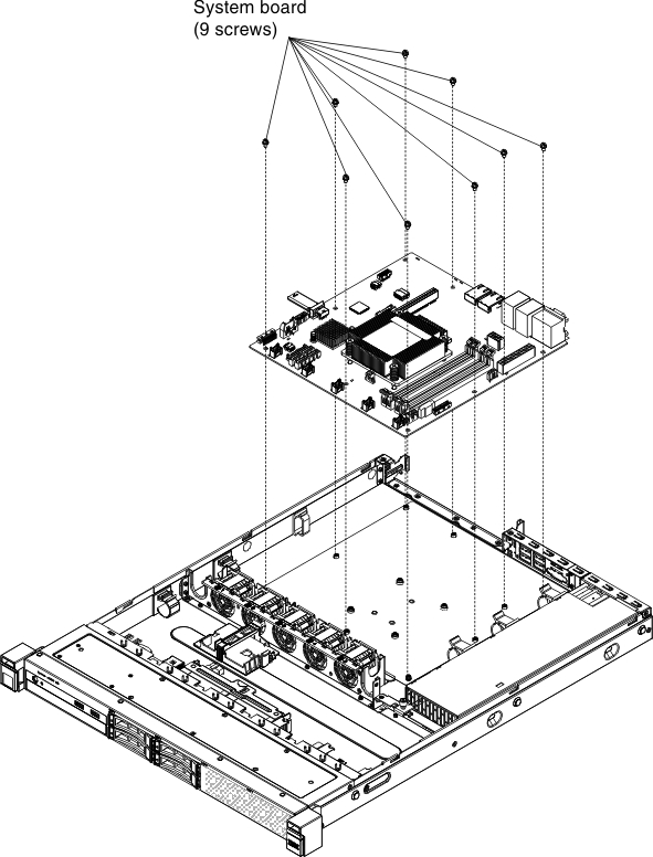
- Align the system board with the chassis and replace the nine screws that you removed. Figure 1. System board installation
Give feedback