Rear view
The following illustrations show the connectors and LEDs on the rear of the server.
The following illustration shows the LEDs and connectors on the rear of the fixed power-supply model.
Figure 1. Connectors on the rear of the fixed power-supply model
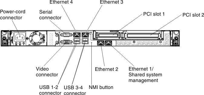
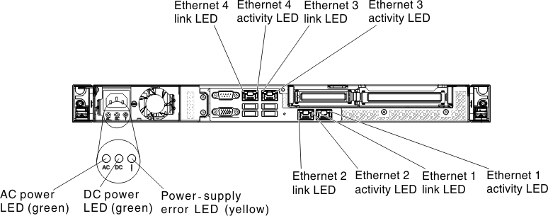
Figure 2. LEDs on the rear of the fixed power-supply model
The following illustration shows the LEDs and connectors on the rear of the redundant power-supply model.
Figure 3. Connectors on the rear of the redundant power-supply model
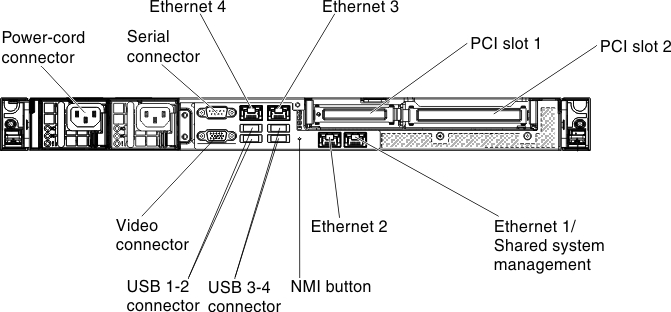
Figure 4. LEDs on the rear of the redundant power-supply model
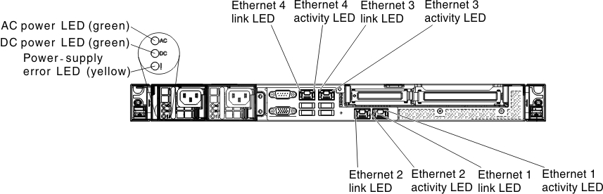
- Ethernet link LEDs: When these LEDs are lit, they indicate that there is an active link connection on the 10BASE-T, 100BASE-TX, or 1000BASE-TX interface for the Ethernet port.
- Ethernet activity LEDs: When these LEDs are lit, they indicate that there is activity between the server and the network.
- AC power LED: This green LED provides status information about the power supply. During typical operation, both the ac and dc power LEDs are lit. For any other combination of LEDs, see Power-supply LEDs.
- DC power LED: This green LED provides status information about the power supply. During typical operation, both the ac and dc power LEDs are lit. For any other combination of LEDs, see Power-supply LEDs.
- Power supply error LED: When this yellow LED is lit, it indicates that the power supply has failed.
- Power cord connector: Connect the power cord to this connector.
- Video connector: Connect a monitor to this connector.
- Serial connector: Connect a 9-pin serial device to this connector. The serial port is shared with the Integrated Management Module II (IMM2). The IMM2 can take control of the shared serial port to redirect serial traffic, using Serial over LAN (SOL).
- USB connectors: Connect a USB device, such as a USB mouse, keyboard, or other device to any of these connectors.
- Ethernet connectors: Use either of these connectors to connect the server to a network. When you use the Ethernet 1 connector, the network can be shared with the IMM2 through a single network cable.
- NMI button: Press this button to force a nonmaskable interrupt to the microprocessor. It allows you to blue screen the server and take a memory dump (use this button only when directed by the Lenovo service support). You might have to use a pen or the end of a straightened paper clip to press the button.
- PCI slot 1: Dedicated to ServeRAID H1110 SAS/SATA controller
- PCI slot 2: Support one PCI Express Gen3 x8 half-length, full-height adapter
Give feedback