
Installing the system board

Before you start, notice the following information:
  • After you reassemble the components in the server, route all cables carefully so that they are not exposed to excessive pressure.
  • When you install the system board, ensure that you remove the Integrated Management Module 2.1 (IMM2.1) Advanced Upgrade from the failing system board and place it on the new system board. For information about the Advanced Upgrade, see Using the remote presence and blue-screen capture features.
  • Some cluster solutions require specific code levels or coordinated code updates. If the device is part of a cluster solution, verify that the latest level of code is supported for the cluster solution before you update the code.
To install the system board, do the following:
  1. Touch the static-protective package that contains the system board to any unpainted metal surface on the server; then, remove the system board from the package.
    Note
    When you are holding or installing the system board in the server, avoid touching the cable clips on the side of the chassis and the connectors on the system board. Do not damage any surrounding components inside the chassis.
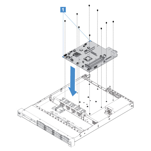
  2. Hold the two corners 1 of the system board carefully, align the screw holes in the system board with the corresponding mounting studs on the chassis, and then install the nine screws that you removed.
    Figure 1. System board installation
    System board installation

  3. Install any of the following components that you removed from the failing system board:
    Note
    Make sure that none of the server cables are caught under the system board.
    1. Microprocessor and heat sink (see Installing the microprocessor and heat sink (Trained technician only))
    2. DIMMs (see Installing a DIMM)
    3. Adapters (see Installing an adapter)
    4. The RAID battery holder (see Installing flash power module holder).
  4. Complete the parts replacement. See Completing the parts replacement.
  5. Remove the microprocessor socket cover from the new system board and install it onto the failing system board.
  6. Start the Setup Utility and reset the configuration.
    1. Set the system date and time.
    2. Set the power-on password.
    3. Reconfigure the server.

    For more information, see Using the Setup Utility program.

  7. Either update the server with the latest RAID firmware or restore the pre-existing firmware from a CD image. See Updating the firmware.
  8. Update the UUID. See Updating the Universal Unique Identifier (UUID).
  9. Update the DMI/SMBIOS. See Updating the DMI/SMBIOS data.
  10. Reactivate FoD. To activate FoD and install activation keys automatically, refer to the instructions is in the Features on Demand User's Guide. To download the document, go to the Lenovo Features on Demand website, log in, and click Help.