Operator information panel
The following illustration shows the controls and LEDs on the operator information panel.
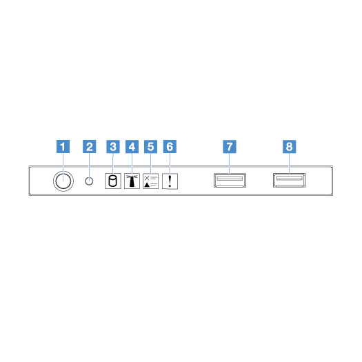
| 1 Power-control button and power-on LED | Press this button to turn on or turn off the server manually. The states of the power-on LED are as follows:
|
| 2 Reset button | Press this button to reset the server and run the power-on self-test (POST). You might have to use a pen or the end of a straightened paper clip to press the button. |
| 3 Hard disk drive activity LED | When this LED is flashing, it indicates that the associated hard disk drive is in use. |
| 4 System-locator LED | Use this blue LED to locate the server among other servers visually. This LED is also used as a presence detection button. You can use Lenovo XClarity Administrator to light this LED remotely. |
| 5 Check log LED | When this yellow LED is lit, it indicates that a system error has occurred. Check the event log for additional information. For more information, see Event logs. |
| 6 System-error LED | When this yellow LED is lit, it indicates that a system error has occurred. For more information, see Event logs. |
| 7 USB connector 1 8 USB connector 2 | Connect a USB device, such as a USB mouse, keyboard, or other device to any of these connectors. |