System-board switches and jumpers
The following illustration shows the location and description of the switches, jumpers, and buttons.
Important
- Before you change any switch settings or move any jumpers, turn off the server; then, disconnect all power cords and external cables. Review the information in Safety, Installation guidelines, and Turning off the server.
- Any system-board switch or jumper block that is not shown in the illustrations in this document are reserved.
- If there is a clear protective sticker on the top of the switch blocks, you must remove and discard it to access the switches.
Figure 1. Location of the switches, jumpers, and buttons on the system board. (cy1cd021a)
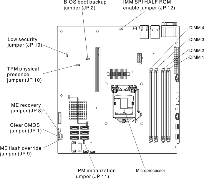
The following table describes the jumpers on the system board.
| Jumper number | Jumper name | Jumper setting |
|---|---|---|
| JP1 | Clear CMOS jumper |
|
| JP2 | BIOS block backup jumper |
|
| JP8 | ME recovery jumper |
|
| JP9 | ME flash override jumper |
|
| JP10 | Trusted Platform Module (TPM) physical presence jumper | Pins 1 and 2: Enable TPM physical presence (default) Pins 2 and 3: Disable TPM physical presence |
| JP11 | TPM initialization jumper |
|
| JP12 | IMM SPI half ROM enable |
|
| JP19 | Low security_N jumper |
|
Note
| ||
Give feedback