The following graphics and descriptions identify the various hardware components and port locations for the control enclosure and the expansion enclosure. Each enclosure takes up the full 2U height in the rack.
See the "Lenovo Storage V7000 hardware components" topic in the Lenovo Storage V7000 Information Center for the full descriptions of the hardware components.
Each enclosure has drives that are
located on the front. Figure 1 and Figure 2 show
the front of an enclosure that has space for up to 12 or 24 drives 2, depending on the model, and a left end cap 1 and
a right end cap 3.
Figure 1. 24 drives and two end caps


Figure 2. Lenovo Storage V7000 Gen1 12 drives and two end
caps


Control enclosure components
Figure 3 shows
the rear view of a control enclosure and identifies the location of
the power supply units and the canisters.
Figure 3. Rear view of a model 2076-112 or a model 2076-124 control enclosure


- Power supply units are located on the left and right of the canisters.
Each unit contains a battery. Power supply 1 is located on
the left. Power supply 2 is located on the right. Power supply 1 is inserted top side up, and power supply 2 is inverted,
or top side down.Important: The power supply units for the control enclosure and expansion enclosure are not interchangeable.
- Two canisters are housed in the middle of the enclosure. Each canister is known as an expansion canister. The upper canister, as shown in Figure 3, is canister 3, and the lower canister is canister 4. Canister 3 is top side up, and canister 4 is inverted, or top side down.
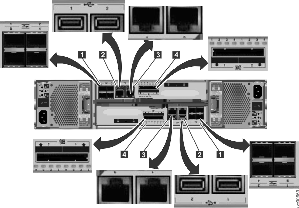
Figure 4 shows
the rear view of a model 2076-112 or a model 2076-124 control enclosure
and identifies the location of the ports.
Figure 4. Data ports and LEDs in the rear of the control enclosure


- 1 Fibre Channel ports. Each canister has four Fibre Channel ports. They are in a block of four in two rows of two connectors. The ports are numbered 1 - 4 from left to right, top to bottom. Their use is optional.
- 2 USB ports. Each canister has two USB ports. The ports are side by side on the canister and are numbered 1 on the left and 2 on the right. One port is used during installation.
- 3 Ethernet ports. Each canister has two Ethernet ports. The ports are side by side on the canister. They are numbered 1 on the left and 2 on the right on the upper canister. The port locations are inverted for the lower canister. Port 1 must be connected first; the use of port 2 is optional.
- 4 Serial-attached SCSI (SAS) ports. Each canister has two SAS ports. The ports are side by side on the canister. They are numbered 1 on the left and 2 on the right. Port 1 must be connected first if you are adding one expansion enclosure. Port 2 must be connected if you are adding a second expansion enclosure.
Note: The reference to the left and right locations applies to
canister 1, which is the upper canister. The port locations are inverted for canister 2, which is the
lower canister.
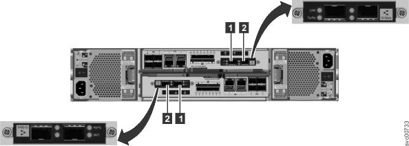
Figure 5 shows the rear view of a model 2076-312 or a model 2076-324
control enclosure with the optional 10 Gbps Ethernet ports installed.
All other ports remain the same.
Figure 5. 10 Gbps Ethernet ports on the rear of the Storwize V7000 enclosure


- 1 10 Gbps Ethernet port 3 which is the left port.
- 2 10 Gbps Ethernet port 4 which is the right port.
Expansion enclosure components
Figure 6 shows
the rear view of an expansion enclosure and identifies the location
of the power supply units and the canisters. The ports and their use
are described later in this section.
Figure 6. Rear view of a model 2076-212 or a model 2076-224 expansion
enclosure


- Power supply units are on the left and right of the canisters.
Power supply 1 is located on the left. Power supply 2 is located on the right. Power supply 1 is inserted top side up,
and power supply 2 is inverted, or top side down.Important: The power supply units for the control enclosure and expansion enclosure are not interchangeable.
- Two canisters are housed in the middle of the enclosure. Each canister is known as an expansion canister. The upper canister, as shown in Figure 6, is canister 3, and the lower canister is canister 4. Canister 3 is top side up, and canister 4 is inverted, or top side down.
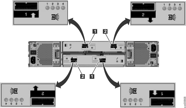
Figure 7 shows
the rear view of an expansion enclosure and identifies the SAS port
locations.
Figure 7. SAS ports and LEDs in rear of expansion enclosure

Each canister has two SAS ports that are numbered 1 on the left 1 and 2 on the right 2. Port 1 must be connected if
you are adding one expansion enclosure. Port 2 must be connected if
you are adding a second expansion enclosure.
Note: The reference to
the left and right locations applies to canister 1, which is the upper canister. The port locations are inverted for canister 2, which is the
lower canister.
Miscellaneous hardware
The USB flash drive is packaged with the publications and contains the initialization tool for performing the initial system configuration.