This topic is divided into two procedures; the first one, powering on an expansion enclosure; the second one, powering on a control enclosure.
Attention: Do not
operate the system when the drive assemblies are missing. Drive assemblies
that are missing disrupt the airflow; the drives do not receive sufficient
cooling. You must insert blank carriers into unused drive bays.
Powering on an expansion enclosure:
Figure 1 shows the location of the LEDs on the power supply units
in the rear of the expansion enclosure.
Figure 1. LEDs on the power supply units of the expansion enclosure
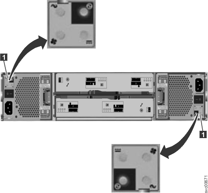
| Hardware component | LED name and symbol | If power on and no fault is detected |
|---|---|---|
| Left enclosure end cap, front of enclosure | Power, top  |
LED is on. |
Fault, middle  |
LED is off. | |
Identify, bottom  |
LED is off. | |
| Expansion canister, rear. The reference to the top and bottom locations applies to canister 1, which is the upper canister. The LED locations are inverted for canister 2, which is the lower canister. | Canister status, top  |
LED is on. |
Fault status, bottom  |
LED is off. | |
| Power supply unit, expansion enclosure. The reference to the left and right locations applies to power supply unit 1, which is the left power supply. The LED locations are inverted for power supply unit 2, which is the right power supply. | Power supply, upper right  |
LED is on. |
Fan failure  |
LED is off. | |
DC power failure  |
LED is off. | |
AC power failure |
LED is off. |
Powering on a control enclosure:
- Power on the control enclosure, if it is not already powered on and configured. Use the power switch on each of the two power supply units, located in the back of the enclosure.
- Use Table 2 to verify the state of the LEDs on the system. Verify that no faults are detected.
Figure 2 shows
the location of the LEDs on the power supply units in the rear of
the control enclosure.
Figure 2. LEDs on the power supply units of the control enclosure
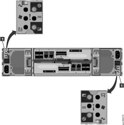
| Hardware component | LED name | If power on and no fault is detected |
|---|---|---|
| Left enclosure end cap, front of enclosure | Power, top |
LED is on. |
| Fault, middle |
LED is off. | |
| Identify, bottom |
LED is off. | |
| Node canister, rear. The reference to the top and bottom locations applies to canister 1, which is the upper canister. The LED locations are inverted for canister 2, which is the lower canister. | Fibre Channel port | If the Fibre Channel port is used: One or more LEDs are on or flashing per port. The LEDs are located between the Fibre Channel ports. The arrow-shaped LEDs point toward the affected port. |
| Ethernet port, if used | One or more LEDs are on per port. | |
| SAS ports | When a SAS port is functioning correctly, all four green LEDs above the port are on. If no cable is plugged into the port, or if the canister at either end of the cable is not yet fully started, the LEDs are not on. | |
| System status, left |
LED is flashing or on. The status is on if the node canister is an active member of a clustered system. The LED is flashing if the node canister is in service or candidate state. If the LED is off, the node canister might still be booting up. Wait up to 5 minutes for the node canister to complete booting up. | |
| Fault status, middle |
LED is off. | |
Power status, right  |
LED is on. | |
| Power supply unit, control enclosure. The reference to the left and right locations applies to power supply unit 1, which is the left power supply. The LED locations are inverted for power supply unit 2, which is the right power supply. | Power supply, upper right |
LED is on. |
| AC power failure |
LED is off. | |
| DC power failure |
LED is off. | |
| Fan failure |
LED is off. | |
Battery failure  |
LED is off | |
Battery good, lower right  |
LED is on or flashing. |
Attention: Do not go to the next section until
the LEDs are in the required states.
See the "Troubleshooting" topic that helps you understand the system status using the LEDs.