Apply the following configuration details for Fibre Channel (FC) and Fibre Channel Over Ethernet (FC/FCoE Gateway, FCF) switches to ensure that you have a valid configuration.
Configuring your SAN with at least two independent switches, or networks of switches, ensures a redundant fabric with no single point of failure. If one of the two SAN fabrics fails, the configuration is in a degraded mode, but is still valid.Maintain separate fabrics for FCoE and FC. If you attempt to combine these fabrics, you might risk adding more paths to the volumes. Supported configurations allow a maximum of eight paths. A SAN with only one fabric is a valid configuration but risks loss of access to data if the fabric fails. SANs with only one fabric are exposed to a single point of failure.
For Fibre Channel connections, the node canisters must be connected to either SAN switches or directly connected to a host port. If the system contains more than one control enclosure, a minimum of two Fibre Channel ports from each node canister must be connected to the SAN. This configuration provides connections to each of the counterpart SANs that are in the redundant fabric. When iSCSI hosts are attached to node canisters, Ethernet switches must be used.
All back-end storage systems must always be connected to SAN switches only. Multiple connections are permitted from redundant storage systems to improve data bandwidth performance. A connection between each redundant storage system and each counterpart SAN is not required. For example, in an IBMDS4000 configuration that contains two redundant storage systems, only two storage system minihubs are usually used. Storage system A is connected to counterpart SAN A, and storage system B is connected to counterpart SAN B. Any configuration that uses a direct physical connection between the node and the storage system is not supported.
When you attach a node to a SAN fabric that contains core directors and edge switches, connect the node ports to the core directors. Then, connect the host ports to the edge switches. In this type of fabric, the next priority for connection to the core directors is the storage systems, leaving the host ports connected to the edge switches.
A SAN must follow all switch manufacturer configuration rules, which might place restrictions on the configuration. Any configuration that does not follow switch manufacturer configuration rules is not supported.
Mixing manufacturer switches in a single SAN fabric
Within an individual SAN fabric, only mix switches from different vendors if the configuration is supported by the switch vendors. When you use this option for FCF Switch to FC Switch connectivity, review and plan as documented in ISL oversubscription.
Fibre Channel switches and interswitch links
The system supports distance-extender technology, including dense wavelength division multiplexing (DWDM) and Fibre Channel over IP (FCIP) extenders, to increase the overall distance between local and remote clustered systems (systems). If this extender technology involves a protocol conversion, the local and remote fabrics are regarded as independent fabrics, limited to three ISL hops each.
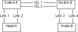
With ISLs between nodes in the same system, the inter-switch links (ISLs) are considered a single point of failure. Fabric with ISL between nodes in a system illustrates this example.
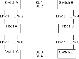
To ensure that a Fibre Channel link failure does not cause nodes to fail when ISLs are between nodes, you must use a redundant configuration. This configuration is illustrated in Fabric with ISL in a redundant configuration. With a redundant configuration, if any one of the links fails, communication on the system does not fail.
Fibre Channel over Ethernet servers and system connections to the existing Fibre Channel SAN
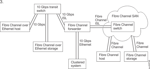
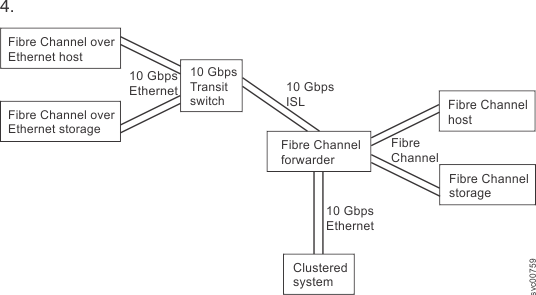
FCoE servers and systems can be connected in several different ways. The following examples show the various supported configurations.
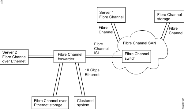
Fibre Channel forwarder linked to existing Fibre Channel SAN shows a system that is connected to a Fibre Channel forwarder switch along with any FCoE hosts and FCoE storage systems. The connections are 10 Gbps Ethernet. The Fibre Channel forwarder is linked to the existing Fibre Channel SAN by using Fibre Channel ISLs. Any Fibre Channel hosts or storage systems remain on the existing Fibre Channel SAN. The connection to the system can be via the SAN (if the system is connected via Fibre Channel) or via the Fibre Channel forwarder switch to the FCoE ports on the system.
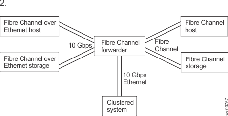
The second example, Fibre Channel forwarder linked to hosts and storage systems without an existing Fibre Channel SAN, is almost the same as the first example but without an existing Fibre Channel SAN. It shows a system that is connected to a Fibre Channel forwarder switch along with any FCoE hosts and FCoE storage systems. The connections are 10 Gbps Ethernet.
In the third example, Fibre Channel host connects into the Fibre Channel ports on the Fibre Channel forwarder, a Fibre Channel host connects into the Fibre Channel ports on the Fibre Channel forwarder. The system is connected to a Fibre Channel forwarder switch along with any FCoE storage systems. The connections are 10 Gbps Ethernet. The Fibre Channel forwarder is linked to the existing Fibre Channel SAN by using Fibre Channel ISLs. Any Fibre Channel hosts or storage systems remain on the existing Fibre Channel SAN. The FCoE host connects to a 10 Gbps Ethernet switch (transit switch) that is connected to the Fibre Channel forwarder.
The fourth example, Fibre Channel host connects into the Fibre Channel ports on the Fibre Channel forwarder without an existing Fibre Channel SAN., is about the same as the previous example but without an existing Fibre Channel SAN. The Fibre Channel hosts connect to Fibre Channel ports on the Fibre Channel forwarder.
ISL oversubscription
Complete a thorough SAN design analysis to avoid ISL congestion. Do not configure the SAN to use system to system traffic or a system to storage system traffic across ISLs that are oversubscribed. For host to system traffic, do not use an ISL oversubscription ratio that is greater than 7 to 1. Congestion on the ISLs can result in severe performance degradation and I/O errors on the host.
The system in a SAN with director class switches
You can use director class switches within the SAN to connect large numbers of RAID controllers and hosts to a system. Because director class switches provide internal redundancy, one director class switch can replace a SAN that uses multiple switches. However, the director class switch provides only network redundancy; it does not protect against physical damage (for example, flood or fire), which might destroy the entire function. A tiered network of smaller switches or a core-edge topology with multiple switches in the core can provide comprehensive redundancy. This configuration provides more protection against physical damage for a network in a wide area. Do not use a single director class switch to provide more than one counterpart SAN because this configuration does not constitute true redundancy.