You can install a pair of cache memory upgrades while the Lenovo Storage V3700 V2 XP, Lenovo Storage V5030, or Lenovo Storage V5030F system is operational.
A Lenovo Storage V3700 V2 XP system can be upgraded to 16 GB of memory. Lenovo Storage V5030 and Lenovo Storage V5030F systems can be upgraded to 32 GB of memory.
Notes:
- Before you add extra RAM, you must remove the node canister from the system configuration by using the CLI or GUI. The following procedure includes details on removing the node canister from the system configuration.
- When a canister is missing, operate the enclosure for as little time as possible. When a canister is missing, the airflow in the enclosure is disrupted. As a result, the system can overheat if it is left that way for too long.
- Memory modules are susceptible to electrostatic discharges.
- If you add extra RAM for an I/O group that is using compression, you must complete a warm start on both nodes in the I/O group for the changes to affect compressed I/O.
Complete the following steps to install a pair of options while the system continues to perform I/O operations.
- Note the service IP addresses of each node canister.
- In the management GUI, check the Recommended Action event log view. Resolve any issues before you continue the procedure.
- Remove the node canister from the
system configuration. In the management GUI, right-click the node
canister and select Remove. Alternately, use
the svctask rmnode command from the CLI.
If volumes are reported as dependent on the node canister, do not continue until you resolve the dependency.
- Remove the node canister safely without disrupting I/O. Refer to Procedure: Removing a node canister
- Remove the lid from the canister.
For instructions, refer to Procedure: Removing and replacing lid of a node canister.
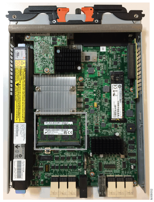
- Locate memory slot 2, which is next to the
battery, under a large heat sink (Locating the memory slot).
Figure 1. Locating the memory slot

- Open the retaining clip on each end of the DIMM connector.
Attention: To avoid breaking the retaining clips or damaging the DIMM connectors, open and close the clips gently.
- Touch the static-protective package that contains the DIMM to any unpainted metal surface on the outside of the canister.
- Remove the DIMM from the package.
- Turn the DIMM so that the DIMM keys align correctly with the connector.
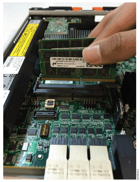
- Insert the DIMM into the connector by aligning the edges
of the DIMM with the slots at the ends of the DIMM connector. DIMMs
do not stand up; rather, they lie in a cascading fashion (Inserting the DIMM into the memory slot).
Figure 2. Inserting the DIMM into the memory slot

- Firmly press the DIMM straight down into the connector
by applying pressure on both ends of the DIMM simultaneously.
The retaining clips snap into the locked position when the DIMM is firmly seated in the connector.Note: If a gap exists between the DIMM and the retaining clips, the DIMM is not inserted correctly. Open the retaining clips, remove the DIMM, and reinsert it.
- Reinstall the lid on the canister.
For instructions, refer to Procedure: Removing and replacing lid of a node canister.
- Reinstall the canister in the enclosure
and replace cables that were removed.
Do not attempt to restart any host systems until instructed to do so.The canister restarts in service mode.
- Use the service
assistant GUI to exit service mode, or use the satask stopservice command from the CLI.
The node canister restarts and joins the system configuration. Before you continue, check that the management GUI monitoring view shows both node canisters online. If node error 841 is displayed, the node was not removed from the system configuration in step #V3500_hw_upgrade_adding_2_cache_upgrades_operational/remove_from_cfg. In that case, remove the node from the system configuration, wait for the node to enter service mode, and then exit service mode to bring the node back online.
- Repeat steps #V3500_hw_upgrade_adding_2_cache_upgrades_operational/remove_from_cfg to #V3500_hw_upgrade_adding_2_cache_upgrades_operational/accept_changes for the second canister.
Verify that host systems rediscovered the first canister so they can fail over it when the second canister is removed.
- Restart any host applications that you stopped earlier.
After the mismatched hardware error 1470 clears automatically, both nodes are successfully running with the additional RAM.
- Use the Recommended Action in the management GUI monitoring page to complete the system update procedure.
- Check the event log for any new alerts. Resolve them using the information in Recommended Action.