The following zoning examples describe ways for zoning a switch. In the examples, a list of port names that are inside brackets ([]) represent a single zone whose zone members are the list of ports shown.
Example 1
Consider the SAN environment
in the following example:
- Two nodes (nodes A and B)
- Nodes A and B each have four ports
- Node A has ports A0, A1, A2, and A3
- Node B has ports B0, B1, B2, and B3
- Two hosts that are called P and Q
- Each of the two hosts has two ports, as described in Two hosts and their ports.
Table 1. Two hosts and their ports P Q P0 Q0 P1 Q1 - Two switches that are called X and Y
- Two storage systems I and J
- Each of the two storage systems has
ports as described in Two storage systems and their ports.
Table 2. Two storage systems and their ports I J I0 J0 I1 J1 I2 I3
- Attach half the host and node ports 1 (A0, A1, B0, B1, P0, Q0) to switch X.
- Attach half the host and node ports 3 (A2, A3, B2, B3, P1, Q1) to switch Y.
- Attach half the storage system ports (I0, I1, J0) to switch X.
- Attach half the storage system ports (I2, I3, J1) to switch Y.
- Create one zone per host port (one port per
node) on switch X:
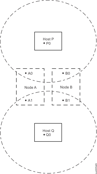
- [A0, B0, P0]
- [A1, B1, Q0]
An example of a host zone illustrates this example.
Figure 1. An example of a host zone
- Create one storage zone per storage system on
switch X:
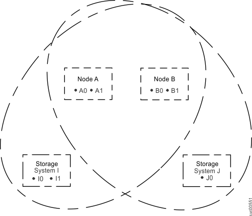
- [A0, A1, B0, B1, I0, I1]
- [A0, A1, B0, B1, J0]
An example of a storage system zone illustrates this example.
Figure 2. An example of a storage system zone
- Create one internode zone on switch X:
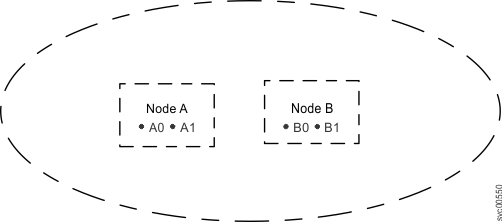
- [A0, A1, B0, B1]
An example of a system zone illustrates this example.
Figure 3. An example of a system zone
- Follow the same steps #svc_zoningaswitch_22n6zd/switchctrrpeat through #svc_zoningaswitch_22n6zd/switchxinter to create the
following list of zones for switch Y: One zone per host port:
- [A2, B2, P1]
- [A3, B3, Q1]
Storage zone:- [A2, A3, B2, B3, I2, I3]
- [A2, A3, B2, B3, J1]
One internode zone:- [A2, A3, B2, B3]
Example 2
The following example describes
a SAN environment that is like the previous example except for the
addition of four hosts that have two ports each.
- Two nodes that are called A and B
- Nodes A and B have four ports each
- Node A has ports A0, A1, A2, and A3
- Node B has ports B0, B1, B2, and B3
- Six hosts that are called P, Q, R, S, T, and U
- Four hosts have four ports each and the other two hosts have two
ports each as described in Six hosts and their ports.
Table 3. Six hosts and their ports P Q R S T U P0 Q0 R0 S0 T0 U0 P1 Q1 R1 S1 T1 U1 P2 Q2 R2 S2 P3 Q3 R3 S3 - Two switches that are called X and Y
- Three storage systems
- Each storage system has
ports as described in
Table 4. Three storage systems and their ports I J K I0 J0 K0 I1 J1 K1 I2 K2 I3 K3 K4 K5 K6 K7
The following tasks comprise a different example configuration:
- Attach half of the host and node ports 1 (A0, A1, B0, B1, P0, P1, Q0, Q1, R0, R1, S0, S1, T0, U0) to switch X.
- Attach half of the host and node ports 1 (A2, A3, B2, B3, P2, P3, Q2, Q3, R2, R3, S2, S3, T1, U1) to switch Y.
- Attach half of the storage system ports (I0, I1, J0, K0, K1, K2, K3) to switch X.
- Attach half of the storage system ports (I2, I3, J1, K4, K5, K6, K7) to switch Y.
- Create one zone per host port (one port per node) on switch X:
- [A0, B0, P0]
- [A1, B1, P1]
- [A0, B0, Q0]
- [A1, B1, Q1]
- [A0, B0, R0]
- [A1, B1, R1]
- [A0, B0, S0]
- [A1, B1, S1]
- [A0, B0, T0]
- [A1, B1, U0]
Attention: Hosts T and U (T0 and U0) and (T1 and U1) are zoned to different ports so that each port is zoned to the same number of host ports. - Create one storage zone per storage system on switch X:
- [A0, A1, B0, B1, I0, I1]
- [A0, A1, B0, B1, J0]
- [A0, A1, B0, B1, K0, K1, K2, K3]
- Create one internode zone on switch X:
- [A0, A1, B0, B1]
- Follow the same steps #svc_zoningaswitch_22n6zd/onezoneswitchx through #svc_zoningaswitch_22n6zd/internodex to create the
following list of zones for switch Y:One zone per host port:
- [A2, B2, P2]
- [A3, B3, P3]
- [A2, B2, Q2]
- [A3, B3, Q3]
- [A2, B2, R2]
- [A3, B3, R3]
- [A2, B2, S2]
- [A3, B3, S3]
- [A2, B2, T1]
- [A3, B3, U1]
Storage zone:- [A2, A3, B2, B3, I2, I3]
- [A2, A3, B2, B3, J1]
- [A2, A3, B2, B3, K4, K5, K6, K7]
One internode zone:- [A2, A3, B2, B3]