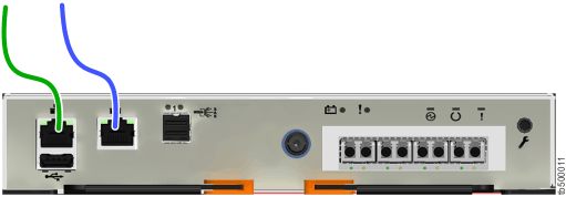
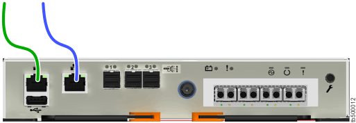
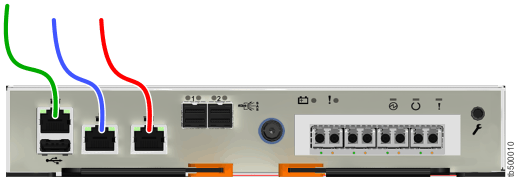
The control enclosures on Lenovo Storage V series systems have several Ethernet ports on the rear of each node canister. The ports provide access to system management facilities and can also provide iSCSI connectivity. The number of ports and their initial function differ across each of the Lenovo Storage V series systems.
To install the Ethernet cables, complete the following steps.
- If you have a Lenovo Storage V3700 V2 or Lenovo
Storage V3700 V2 XP system, complete the following steps.
- Identify the location and function of the Ethernet ports
on your system; refer to Figure 1 and Figure 2.
- Port 1 can be used to provide Ethernet connections; in the figures, port 1 is identified by the green cable.
- Port 2 serves as the technician port when the system is initially
set up or when service is needed. In the figures, port 2 is identified
by the blue cable. After the system initializes, port 2 can also be
used for iSCSI connectivity or IP replication.Note: Do not connect port 2 to a network switch until the system initialization or service is complete. After the system initializes, the technician port is automatically disabled and port 2 can be used for Ethernet connectivity. However, when port 2 is used to perform system service, you must first enter the satask chserviceip -techport disable command to disable the technician port. You can then use port 2 to provide additional Ethernet connectivity. See Technician port for more details.
- Connect Ethernet port 1 of each node canister in the
system to the IP network that will provide a connection to the system
management interfaces.
Figure 1 shows the Ethernet cabling and the ports on the back of a Lenovo Storage V3700 V2 system.
Figure 1. Connecting the Ethernet cables to a Lenovo Storage V3700 V2 system
Figure 2 shows the Ethernet cabling and the ports on the back of a Lenovo Storage V3700 V2 XP system.
Figure 2. Connecting the Ethernet cables to a Lenovo Storage V3700 V2 XP system
- Optionally, connect Ethernet port 2 of each node canister
in the system to a second IP network, as shown by the blue cable connection
in Figure 1 and Figure 2.
This second port can be used to provide a redundant connection to
the system management interfaces; it can also be used for iSCSI connectivity
to the system by hosts on the network.
Note: On Lenovo Storage V3700 V2 and Lenovo Storage V3700 V2 XP systems, the second Ethernet port is also used as the technician port. Do not connect Ethernet port 2 to the SAN until the management GUI setup wizard completes on each system and the cluster is created. If you have to service your system, disconnect port 2 from the SAN before you enable port 2 to be the technician port again.
- Identify the location and function of the Ethernet ports
on your system; refer to Figure 1 and Figure 2.
- If you have a Lenovo Storage V5030 system, complete the following steps.
- Identify the location and function of the Ethernet ports
on your system; refer to Figure 3.
- The technician port should only be used to initialize or service
the system. In Figure 3, the technician
port is identified by the green cable.Note: Never use the technician port to provide an Ethernet connection to the system. Do not connect the Ethernet technician port to a network switch. The technician port must only be directly connected to a personal computer when initializing a system or servicing a node. See Technician port for more details.
- Ethernet port 1 can be used to provide Ethernet connections. In the figure, port 1 is identified by the blue cable.
- Ethernet port 2 can optionally be used to provide additional Ethernet connections. In the figure, port 2 is identified by the red cable. Port 2 can also be used for iSCSI connectivity or IP replication.
- The technician port should only be used to initialize or service
the system. In Figure 3, the technician
port is identified by the green cable.
- Connect Ethernet port 1 of each Lenovo Storage V5030 node canister in the system to the IP network that will provide
a connection to the system management interfaces. Figure 3 shows
the port locations and Ethernet cabling on a Lenovo Storage V5030 node canister.
Figure 3. Connecting the Ethernet cables to a Lenovo Storage V5030 system

- Optionally, connect Ethernet port 2 of each node canister in the system to a second IP network, as shown by the red cable connection in Figure 3. Port 2 can provide a redundant connection to the system management interfaces. Port 2 can also be used for iSCSI connectivity to the system by hosts on the network. If more than one control enclosure is present in the system, ensure that port 2 of every node canister is connected to the same network to provide access if the configuration node fails.
- Identify the location and function of the Ethernet ports
on your system; refer to Figure 3.