Installing the DVD enablement kit
Use this information to install the DVD enablement kit.
The Lenovo System x3550 M3 DVD enablement kit is used to install an optical drive cage in a server with less than four hard disk drives. The optional optical drive cage is installed in the bays for hot-swap hard disk drives 5 to 8.
The DVD enablement option kit contains the following components:
- One optical drive cage
- One optical drive bay filler panel
- One SATA cable
- One retention bracket
- One bezel and screws
To install the DVD enablement kit, complete the following steps:
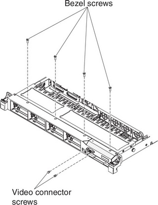
- Remove the screws from the bezel.Figure 1. Screws removal
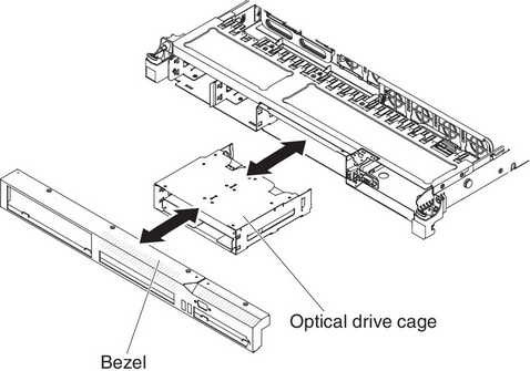
- Slide the optical drive cage forward into the optical drive bay until the screw holes on the drive cage align with the screw holes on the chassis. Figure 2. Optical drive cage installation
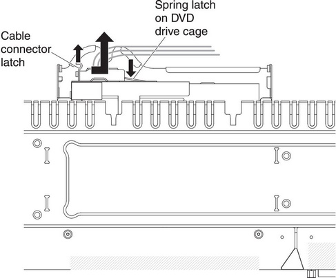
- Pull the cable connector latch up and hold it there while you slide the cable connector to the left; then, slide the cable connector latch down to lock the cable in place.Figure 3. DVD drive cable installation
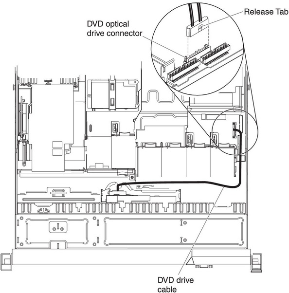
- Connect the other end of the DVD cable to the connector on the system board. The following illustration shows the cable routing for the DVD cable: The DVD cable should go on the top of the operation information panel cable (in the middle) and the Video/USB cable (on the bottom) when all three cables are installed in the server.Figure 4. DVD drive cable connection
If you have other devices to install or remove, do so now. Otherwise, go to Completing the installation.
Give feedback