Replacing a microprocessor and heat sink
Use this information to install a microprocessor and heat sink.
Attention: When you handle static-sensitive devices, take precautions to avoid damage from static electricity. For details about handling these devices, see Handling static-sensitive devices.
Note
- If your server comes with one Intel Pentium 1400 series microprocessor, the second microprocessor socket is not used. The server supports only one Intel Pentium microprocessor. If you plan to install two Intel Xeon microprocessors in the server, you must first remove the Intel Pentium microprocessor that came with the server.
- See Installing an additional microprocessor and heat sink for notes and other information that you must consider when you install a microprocessor.
- Be extremely careful, the pins on the socket are fragile. Any damage to the pins may require replacing the system board.
- Use the microprocessor installation tool that came with the new microprocessor to remove the microprocessor from the server. Failure to use the microprocessor tool may cause damage to the pins on the socket. Any damage to the pins may require replacing the system board.
To install an additional microprocessor and heat sink, complete the following steps:
- Read the safety information that begins in Safety and Installation guidelines.
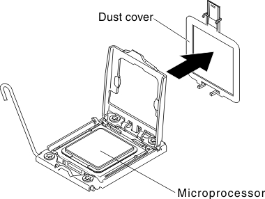
- Remove the socket cover from the microprocessor socket, if it is installed.Figure 1. Mmcroprocessor socket cover removal
- If the microprocessor is preinstalled in the installation tool, release the sides of the cover and remove the cover from the installation tool; then, continue to step 5.
- Install the microprocessor in the microprocessor installation tool:
- Remove the static-protective bag, and the foam surrounding the bag, from the box.
- Touch the static-protective package that contains the new microprocessor to any unpainted metal surface on the server; then, remove the microprocessor from the package.Attention
- Do not touch the microprocessor contacts; handle the microprocessor by the edges only. Contaminants on the microprocessor contacts, such as oil from your skin, can cause connection failures between the contacts and the socket.
- Handle the microprocessor carefully. Dropping the microprocessor during installation or removal can damage the contacts.
- Do not use excessive force when you press the microprocessor into the socket.
- Make sure that the microprocessor is oriented and aligned and positioned in the socket before you try to close the lever.
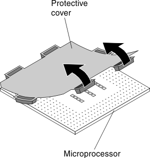
- If there is a plastic protective cover on the bottom of the microprocessor, carefully remove it.Figure 2. Plastic protective cover removal
- Twist the handle of the microprocessor installation tool counterclockwise so that it is in the open position.
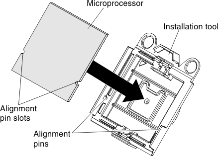
- Align the triangle alignment mark on the microprocessor with the triangle alignment mark on the microprocessor installation tool, then place the microprocessor on the bottom of the tool so that the tool can grasp the microprocessor correctly onto the bottom of the installation tool.
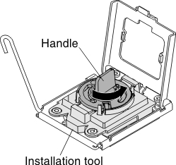
- Align the holes on the microprocessor installation tool with the screws on the microprocessor bracket, then place the microprocessor installation tool down over the microprocessor 1 . Twist the handle clockwise 2 to attach the tool to the microprocessor.Figure 3. Installation tool attachment
- Twist the handle of the installation tool clockwise to secure the microprocessor in the tool.NoteYou can pick up or release the microprocessor by twisting the microprocessor installation tool handle clockwise.
- Install the microprocessor:
- Align the holes on the microprocessor installation tool with the screws on the microprocessor bracket, then place the microprocessor installation tool down over the microprocessor 1 . Twist the handle clockwise 2 to attach the tool to the microprocessor.NoteThe microprocessor fits only one way on the socket.Figure 4. Installation tool alignment
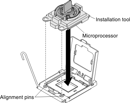
- Twist the handle on the microprocessor tool counterclockwise to insert the microprocessor into the socket.Figure 5. Microprocessor installation
 Attention
- Do not press the microprocessor into the socket.
- Do not touch exposed pins of the microprocessor socket. The pins on the socket are fragile. Any damage to the pins may require replacing the system board.
- Make sure that the microprocessor is oriented and aligned correctly in the socket before you try to close the microprocessor retainer.
- Do not touch the thermal material on the bottom of the heat sink or on top of the microprocessor. Touching the thermal material will contaminate it and destroys its even distribution. If the thermal material on the microprocessor or heat sink becomes contaminated, you must replace the thermal grease.
- Take off the microprocessor installation tool from the microprocessor socket and close the microprocessor bracket frame.
- Carefully close the microprocessor release lever to the closed position to secure the microprocessor in the socket.
- Align the holes on the microprocessor installation tool with the screws on the microprocessor bracket, then place the microprocessor installation tool down over the microprocessor 1 . Twist the handle clockwise 2 to attach the tool to the microprocessor.
- Install the heat sink that comes with the microprocessor:Attention
- Do not set down the heat sink after you remove the plastic cover.
- Do not touch the thermal material on the bottom of the heat sink. Touching the thermal material will contaminate it. If the thermal material on the microprocessor or heat sink becomes contaminated, contact your service technician.
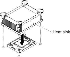
- Remove the plastic protective cover from the bottom of the heat sink.AttentionDo not touch the thermal grease on the bottom of the heat sink after you remove the plastic cover. Touching the thermal grease will contaminate it. See
Thermal grease for more information. - Align the screws on the heat sink with the screw holes on the system board; then, place the heat sink on the microprocessor with the thermal-grease side down.Figure 6. Heat sink installation
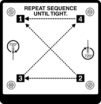
- Press firmly on the captive screws and tighten them with a screwdriver. The follow illustration shows the sequence in tightening the screws, which is also shown on top of the heat sink. Begin with the screw labeled as "1", then "2", "3" and finally "4". If possible, each screw should be rotated two full rotations at a time. Repeat until the screws are tight. Do not overtighten the screws by using excessive force. If you are using a torque wrench, tighten the screws to 8.5 Newton-meters (Nm) to 13 Nm (6.3 foot-pounds to 9.6 foot-pounds).Figure 7. Tighten the captive screws
- If you installed the second microprocessor, install the two fans on Fan connector 4 and Fan connector 6 of the system board respectively (see Replacing a fan).
- Reinstall the memory module that you have removed (see Replacing a memory module).
- Reinstall the air baffle (see Replacing the air baffle).
- Reconnect any cables that you have disconnected from the adapters or system board.
Give feedback