Removing the standard I/O book
Use this information for instructions on how to remove the standard I/O book.
Before you remove the standard I/O book, take the following steps to save data, firmware, and configuration information.
- Record the system configuration information, IMM network settings, system Vital Product Data (VPD), Features on Demand (FoD) inventory and keys, system machine type, system model number, system product identifier, system serial number, Universal Unique Identifier (UUID), and system asset tag of the server. This information can be found in any of the following:
Customer records
Service offering support information
System configuration, VPD and FoD files saved using the Advanced Settings Utility (ASU). For more information about using ASU and additional command options, see Advanced Settings Utility program.
Save system configuration information
Use the following ASU command to save system configuration information:
asu64 save <system_config>where:
<system_config> is the complete path name of the file where the system configuration is to be saved.
Save system VPD information
Use the following ASU command to save system VPD information:
asu64 show SYSTEM_PROD_DATA > <system_vpd>where:
<system_vpd> is the complete path name of the file where the system VPD is to be saved.
Save FoD inventory and key information
Use the following ASU command to save FoD inventory and key information:
asu64 fodcfg reportkey
asu64 fodcfg exportkey
- Save the system-event log to external media.
- Record the existing front operator panel assembly part number and FRU part number. This information is required to update component VPD stored in the standard I/O book and can be found in any of the following:
Customer records
Service offering support information
Component VPD file saved using the Advanced Settings Utility (ASU). For more information about using ASU and additional command options, see Advanced Settings Utility program.
Save component VPD information
Use the following ASU command to save component VPD information:
asu64 show VPD > <component_vpd>where:
<component_vpd> is the complete path name of the file where the component VPD information is to be saved.
The front operator panel assembly is the component with extension “.3” in the saved component VPD file.
Existing front operator panel assembly 11S and FRU barcode information. For more information about accessing the existing front operator panel assembly 11S and FRU barcode information, see Removing the front operator panel assembly and Replacing the front operator panel assembly.
- Record the existing LCD system information display panel part number, FRU part number, serial number and prefix serial number. This information is required to update component VPD stored in the standard I/O book and can be found in any of the following:
Customer records
Service offering support information
Component VPD file saved using the Advanced Settings Utility (ASU). For more information about using ASU and additional command options, see Advanced Settings Utility program.
Save component VPD information
Use the following ASU command to save component VPD information:
asu64 show VPD > <component_vpd>where:
<component_vpd> is the complete path name of the file where the component VPD information is to be saved.
The LCD system information display panel is the component with extension “.4” in the saved component VPD file.
Existing LCD system information display panel 11S and FRU barcode information. For more information about accessing the existing LCD system information display panel 11S and FRU barcode information, see Removing the LCD system information display panel and Replacing the LCD system information display panel.
- Record the existing midplane part number, FRU part number, serial number and prefix serial number. This information is required to update component VPD stored in the standard I/O book and can be found in any of the following:
Customer records
Service offering support information
Component VPD file saved using the Advanced Settings Utility (ASU). For more information about using ASU and additional command options, see Advanced Settings Utility program.
Save component VPD information
Use the following ASU command to save component VPD information:
asu64 show VPD > <component_vpd>where:
<component_vpd> is the complete path name of the file where the component VPD information is to be saved.
The 4-socket midplane is the component with extension “.1” and the 8-socket midplane is the component with extension “.2” in the saved component VPD file.
Existing midplane 11S and FRU barcode information. For more information about accessing the existing midplane 11S and FRU barcode information, see Removing the midplane and Replacing the midplane.
To remove the standard I/O book, complete the following steps:
- Before you begin, read Safety and Installation guidelines.
- Turn off the server (see Turning off the server) and all attached peripheral devices. Disconnect all power cords; then, disconnect all external cables as necessary to replace the device.
- Disconnect the external cables from the adapters.
- Rotate the release latches on the handles toward you, then rotate the handles on the standard I/O book all the way down to release the module from the midplane.
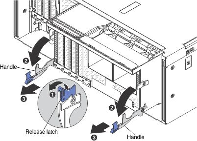
- Slide the standard I/O book out of the shuttle and set it aside.
- Open the adapter retention lever.
- Remove the adapters from the standard I/O book board (see Removing an adapter).
- Remove the USB hypervisor embedded flash device (see Removing a USB embedded hypervisor flash device).
- Remove any flash power modules (see Removing a RAID adapter flash power module from the standard I/O book).
- Remove the fans (see Removing a hot-swap fan assembly).
- If you are instructed to return the module, follow all packaging instructions, and use any packaging materials for shipping that are supplied to you.