Replacing a microprocessor and heat sink
Use this information to replace a microprocessor and heat sink.
The following notes describe the type of microprocessor that the server supports and other information that you must consider when you install a microprocessor and heat sink:
- The server supports one Intel land grid array (LGA) 1150 dual-core or quad-core microprocessor. The type, speed, and L3 cache of the microprocessor depends on the server model.
- Read the documentation that comes with the microprocessor to determine whether you have to update the server firmware. To download the most current level of server firmware, go to the Lenovo Support Portal and the Fix Central website.
- The microprocessor uses an integrated voltage regulator on the system board.
- The microprocessor speeds are automatically set for this server; therefore, you do not have to set any microprocessor frequency-selection jumpers or switches.
- If the thermal-grease protective cover (for example, a plastic cap or tape liner) is removed from the heat sink, do not touch the thermal grease on the bottom of the heat sink or set down the heat sink. For more information about applying or working with thermal grease, see Thermal grease.NoteRemoving the heat sink from the microprocessor destroys the even distribution of the thermal grease and requires replacing the thermal grease.
Attention
- Microprocessors are to be installed only by trained technicians.
- Do not allow the thermal grease on the microprocessor and heat sink to come in contact with anything. Contact with any surface can compromise the thermal grease and the microprocessor socket.
- Dropping the microprocessor during installation or removal can damage the contacts.
- Do not touch the microprocessor contacts; handle the microprocessor by the edges only. Contaminants on the microprocessor contacts, such as oil from your skin, can cause connection failures between the contacts and the socket.
- The pins on the sockets are fragile. Any damage to the pins might require replacing the system board.
Read the safety information in Safety and Installation guidelines.
If you are replacing a server component in the server, you need to slide the server out from the rack enclosure, turn off the server and peripheral devices, and disconnect the power cords and all external cables.
To install a microprocessor and heat sink, complete the following steps.
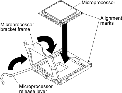
- Align the microprocessor with the socket (note the alignment mark and the position of the notches); then, carefully place the microprocessor on the socket, close the microprocessor bracket frame, and close the microprocessor release latch.Figure 1. Microprocesssor installation
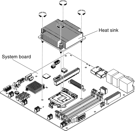
- Align the screw holes on the heat sink with the holes on the system board.Figure 2. Heat sink installation
What to do next
- Install the server into the rack enclosure and push the server into the rack until it clicks into place.
- Reconnect the power cords and any cables that you removed.
- Turn on the peripheral devices and the server.
Give feedback