Connecting the cables
Use this information to connect the cables.
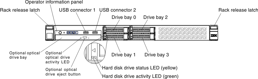
The following illustration shows the locations of the input and output connectors on the front of the server.
Figure 1. Input and output connectors on the front of the 3.5-inch hard disk drive server model
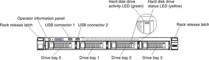
Figure 2. Input and output connectors on the front of the 2.5-inch hard disk drive server model
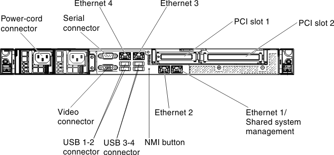
The following illustration shows the locations of the input and output connectors on the rear of the server.
Figure 3. Input and output connectors on the back of the fixed power-supply server model
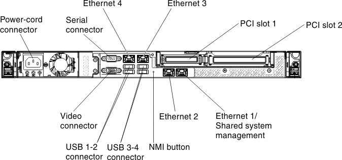
Figure 4. Input and output connectors on the back of the redundant power-supply server model
- You must turn off the server before you connect or disconnect cables.
- See the documentation that comes with any external devices for additional cabling instructions. It might be easier for you to route cables before you connect the devices to the server.
- Cable identifiers are printed on the cables that come with the server and optional devices. Use these identifiers to connect the cables to the correct connectors.
Refer to the Internal cable routing and connectors for internal cable routing information.
Give feedback