System-board switches and jumpers
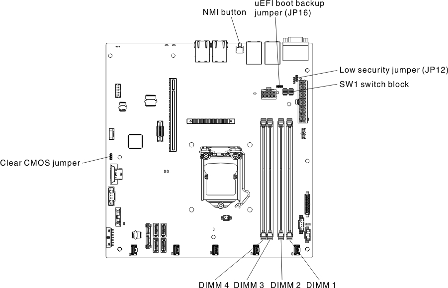
The following illustration shows the location and description of the switches, jumpers, and buttons.
- Before you change any switch settings or move any jumpers, turn off the server; then, disconnect all power cords and external cables. Review the information in Safety, Installation guidelines, and Turning off the server.
- Any system-board switch or jumper block that is not shown in the illustrations in this document are reserved.
- If there is a clear protective sticker on the switch blocks, you must remove and discard it to access the switches.
The following table describes the jumpers on the system board.
| Jumper name | Description |
|---|---|
| Clear CMOS jumper |
|
| Low security jumper (JP12) |
|
| UEFI boot backup jumper (JP16) |
|
Note
| |
The following table describes the functions of the SW1 switch block on the system board.
| Switch number | Default position | Description |
|---|---|---|
| 1 | Off | Asserts TPM physical presence. When this switch is toggled on, the TPM physical presence is asserted. |
| 2 | Off | Power-on password override. Changing the position of this switch bypasses the power-on password check the next time the server is turned on and starts the Setup utility so that you can change or delete the power-on password. You do not have to move the switch back to the default position after the power-on password in overridden. Changing the position of this switch does not affect the administrator password check if an administrator password is set. See Passwords for additional information about passwords. |
| 3 | Off | Default off. |
| 4 | Off | Asserts IMM2 reset. When this switch is toggled on, the IMM2 reset is asserted. |
The following table describes the functions of the button on the system board.
| Button name | Definition |
|---|---|
| NMI button | This button is on the rear of the server. Press this button to force a nonmaskable interrupt to the microprocessor. You might have to use a pen or the end of a straightened paper clip to press the button. You can also use it to force a blue-screen memory dump (use this button only when you are directed to do so by Lenovo Support). |