Installing the microprocessor and heat sink (Trained technician only)
The following notes describe the type of microprocessor that the server supports and other information that you must consider when you install a microprocessor and heat sink:
- The server supports one Intel land grid array (LGA) 1151 dual-core or quad-core microprocessor. The type, speed, and L3 cache of the microprocessor depends on the server model.
- Read the documentation that comes with the microprocessor to determine whether you have to update the server firmware. To download the most current level of server firmware, go to the Lenovo Support Portal and https://datacentersupport.lenovo.com.
- The microprocessor uses an integrated voltage regulator on the system board.
- The microprocessor speeds are automatically set for this server; therefore, you do not have to set any microprocessor frequency-selection jumpers or switches.
- If the thermal-grease protective cover (for example, a plastic cap or tape liner) is removed from the heat sink, do not touch the thermal grease on the bottom of the heat sink or set down the heat sink. For more information about applying or working with thermal grease, see Thermal grease.NoteRemoving the heat sink from the microprocessor destroys the even distribution of the thermal grease and requires reapplying the thermal grease.
Attention
- Do not allow the thermal grease on the microprocessor and heat sink to come in contact with anything. Contact with any surface can compromise the thermal grease and the microprocessor socket.
- Dropping the microprocessor during installation or removal can damage the contacts.
- The microprocessor contacts are fragile. Do not touch the microprocessor contacts; handle the microprocessor by the edges only. Contaminants on the microprocessor contacts, such as oil from your skin, can cause connection failures between the contacts and the socket.
- The pins on the sockets are fragile. Any damage to the pins might require replacing the system board.
- When you handle static-sensitive devices, take precautions to avoid damage from static electricity. For details about handling these devices, see Handling static-sensitive devices.
- The microprocessor fits only one way on the socket.
Removing the heat sink from the microprocessor destroys the even distribution of the thermal grease, you must wipe off the thermal grease with the alcohol wipes and reapply clean thermal grease. See Thermal grease.
To install the microprocessor and heat sink, do the following:
- Install the microprocessor.
- Align the microprocessor with the socket (note the alignment marks 1 and the position of the notches) and carefully place the microprocessor on the socket.
- Close the microprocessor bracket frame.
- Close the microprocessor retention latch by securing the handle back to its position.
Figure 1. Microprocessor installation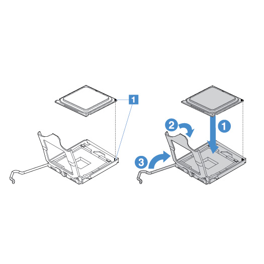
- Install the heat sink on the microprocessor. AttentionDo not touch the thermal grease on the bottom of the heat sink. Touching the thermal grease will contaminate it. If the thermal grease on the microprocessor or heat sink becomes contaminated, you must wipe off the contaminated thermal grease on the microprocessor or heat sink with the alcohol wipes and reapply clean thermal grease to the heat sink.
- Tighten the screws 1 with a screwdriver, alternating among the screws until they are tight. If possible, each screw should be rotated two full rotations at a time. Repeat until the screws are tight. AttentionWhen the two screws that are closer to the rear of the server are tightened, the screw heads are not level with the surface of the heat sink. Do not overtighten the screws by using excessive force.Figure 2. Heat sink installation
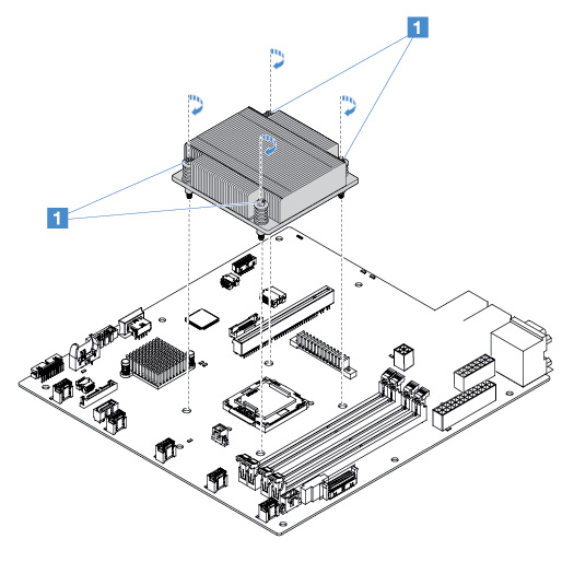
- Tighten the screws 1 with a screwdriver, alternating among the screws until they are tight. If possible, each screw should be rotated two full rotations at a time. Repeat until the screws are tight.
Give feedback