Error LEDs
This section describes the Error LEDs on the system board and the suggested actions to correct the detected problems.
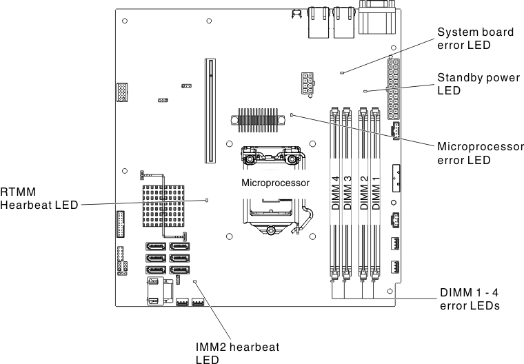
The illustration shows the system-board LEDs. The system board has error LEDs that will help to locate the source of the error. Run the diagnostic programs to find out the cause of the error (see IBM Dynamic System Analysis).
The server is designed so that LEDs remain lit when the server is connected to an ac power source but is not turned on, provided that the power supply is operating correctly. This feature helps you to isolate the problem when the operating system is shut down.
Many errors are first indicated by a lit system-error LED on the control-panel assembly of the server. If this LED is lit, one or more LEDs elsewhere in the server might also be lit and can direct you to the source of the error.
Before you work inside the server to view the LEDs, read the Safety and Handling static-sensitive devices.
- Check the control-panel assembly on the front of the server. If the system-error LED is lit, it indicates that an error has occurred.
- Check the front and rear of the server to determine whether any component LEDs are lit.
- Remove the server top cover and look inside the server for lit LEDs. Certain components inside the server have LEDs that will be lit to indicate the location of a problem. For example, a DIMM error will light the LED next to the failing DIMM on the system board.
- Look at the system service label inside the top cover of the server, which gives an overview of internal components. This information can often provide enough information to correct the error.
| ||
|---|---|---|
| LED | Description | Action |
| DIMM error LEDs | A memory DIMM has failed or is incorrectly installed. |
|
| Microprocessor error LED | Microprocessor has failed, is missing, or has been incorrectly installed. Note (Trained technician only) Make sure that the microprocessor is installed correctly, see |
|
| System-board error LED | System-board CPU VRD and/or power voltage regulators have failed. | (Trained technician only) Replace the system board. |
| IMM2 heartbeat LED | Indicates the status of the boot process of the IMM2. When the server is connected to power this LED flashes quickly to indicate that the IMM2 code is loading. When the loading is complete, the LED stops flashing briefly and then flashes slowly to indicate that the IMM2 if fully operational and you can press the power-control button to start the server. | If the LED does not begin flashing within 30 seconds of when the server is connected to power, complete the following steps:
|
| RTMM heartbeat LED | Power-on and power-off sequencing. |
|