On Lenovo Storage V7000 systems,
the control enclosure has several Ethernet ports present or optionally
present on the rear of each node canister. Ports 1 and 2 provide access
to system management facilities. Ports 1, 2 and 3 on the rear of each
canister can also provide iSCSI connectivity.
To install the Ethernet cables, complete the following
steps.
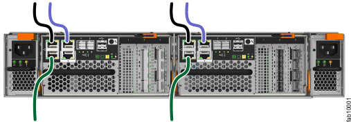
- Connect
Ethernet port 1 of each node canister in the system to the IP network
that will provide connection to the system management interfaces,
as shown in Figure 1.
This port can also be used for iSCSI connectivity to the system
by hosts on the network. Where more than one control enclosure is
present in the system, ensure port 1 of every node canister is connected
to the same network to provide access if the configuration node fails.
Figure 1. Connecting the Ethernet cables
- Optionally, connect Ethernet
port 2 of each node canister in the system to a second IP network
that will provide redundant connection to the system management interfaces,
as shown by the lighter cable connection in Figure 1.
This port can also be used for iSCSI connectivity to the system
by hosts on the network. If there is more than one control enclosure
in the system, ensure that port 2 of every node canister is connected
to the same network to provide access if the configuration node fails.
- Optionally, connect Ethernet
port 3 of both node canisters in a system to the networks that will
provide extra iSCSI connectivity to the system.
Note: Do not connect the Ethernet technician port (labeled T) to a network switch. The technician port must only be directly
connected to a personal computer when initializing a system or servicing
a node.
