The Fibre Channel port LEDs show the speed of the Fibre Channel ports and activity level.
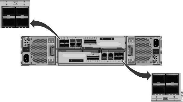
Each node canister has four Fibre Channel ports located on the left side of the canister as shown in Figure 1. The ports are in two rows of two ports. The ports are numbered 1 - 4 from left to right and top to bottom.
Note: The reference
to the left and right locations applies to canister 1, which is the upper canister. The port locations are inverted for canister 2, which is the
lower canister.
Figure 1. Fibre Channel ports on the
node canisters
There are two green LEDs associated with each port: the speed
LED and the link activity LED. These LEDs are in the shape of a triangle.
The LEDs are located in between the two rows of the ports as shown
in Figure 2. Figure 2 shows
the LEDs for the Fibre Channel ports on canister 1. Each LED points
to the associated port. The first and second LEDs in each set show
the speed state, and the third and fourth LEDs show the link state.
Figure 2. LEDs on the Fibre Channel ports
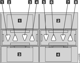
| Associated port | LED location | LED status |
|---|---|---|
| Port 3 3 | First LED between ports 1 and 3 1 | Speed |
| Port 1 1 | Second LED between ports 1 and 3 2 | Speed |
| Port 3 3 | Third LED between ports 1 and 3 3 | Link |
| Port 1 1 | Fourth LED between ports 1 and 3 4 | Link |
| Port 4 4 | First LED between ports 2 and 4 5 | Speed |
| Port 2 2 | Second LED between ports 2 and 4 6 | Speed |
| Port 4 4 | Third LED between ports 2 and 4 7 | Link |
| Port 2 2 | Fourth LED between ports 2 and 4 8 | Link |
Table 2 provides the status descriptions for the LEDs on the Fibre Channel ports.
| Speed state LED | Link state LED | Link state |
|---|---|---|
| Off | Off | Inactive |
| Off | On or flashing | Active low speed (2 Gbps) |
| Flashing | On or flashing | Active medium speed (4 Gbps) |
| On | On or flashing | Active high speed (8 Gbps) |