Plan to attach each of the two power supplies in an enclosure to separate main power supply lines.
Attention: The power cord is the main power disconnect. Ensure
that the socket outlets are located near the equipment and are easily
accessible.
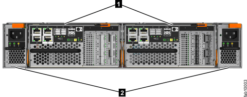
Figure 1 shows the rear view of a Lenovo Storage® V7000 Gen2 control enclosure with the power supplies 2 at either
end of the enclosure.
Figure 1. Rear view of a Lenovo Storage V7000 Gen2 control enclosure with the power supplies


- 1 Node canisters
- 2 Power supply units: power supply 1 (left), power supply 2 (right)
Figure 2 shows the rear view of a control enclosure with the power supplies (1 and 2) at either end of the enclosure:
Figure 2. Rear view of a Lenovo Storage V7000 Gen1 control enclosure with the power supplies (1 and 2).


Plan to connect the power cords of the auto-sensing power supplies on the left side of the rack (when viewed from the rear) to one power source that provides power in the range 100V - 240V ac. Plan to connect the power cords of the power supplies on the right side of the rack to another 100V - 240V ac power source. Using two power sources provides power redundancy.
The power supplies in a control enclosure are not interchangeable with the power supplies in an expansion enclosure.