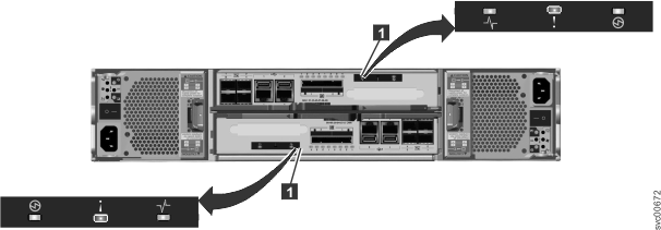
| System status |
Indicates the status of the node.
- The on status indicates that the node is active, that is, it is
an active member of a clustered system. When the node is active, do
not remove it.
- The off state indicates there is no power to the canister or the
canister is in standby mode. These conditions can cause the off state:
- The main processor is off and only the service processor is active.
- A power-on self-test (POST) is running on the canister.
- The operating system is loading.
- The flashing status indicates that the node is in candidate state
or service state. It is not able to perform I/O in a system. When
the node is in either of these states, it can be removed. Do not remove
the canister unless directed by a service procedure.
|
Green |
|
| Fault |
Indicates if a fault is present and identifies
which canister.
- The on status indicates that the node is in service state or an
error exists that might be preventing the code from starting. Do not assume that this status indicates a hardware
error. Further investigation is required before replacing the node
canister.
- The off status indicates that the node is a candidate or is active.
This status does not mean that there is not a hardware error on the
node. Any error that was detected is not severe enough to stop the
node from participating in a system.
- The flashing status indicates that the canister is being identified.
This status might or might not be a fault.
|
Amber |
|
| Power |
Indicates if power is available and the boot
status of the canister.
- The on status indicates that the canister is powered on and that
the main processor or processors are running.
- The off status indicates that no power is available.
- The slow flashing (1 Hz) status indicates that power is available
and that the canister is in standby mode. The main processor or processors
are off and only the service processor is active.
- The fast flashing (2 Hz) indicates that the canister is running
the power-on self-test (POST).
|
Green |
|
Notes:
- If the system status LED is on and the fault LED is off, the node
canister is an active member of a system.
- If the system status LED is on and the fault LED is on, there
is a problem establishing a system.
For a more complete identification of the
system LEDs, follow the procedure for understanding the system status
using the LEDs.
|


