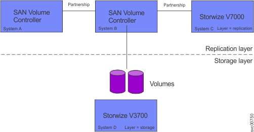
Partnerships define an association between a local system and a partner system.
Before a Metro Mirror or Global Mirror relationship or consistency group can be created with a remote system, a partnership between the two systems must be established. If Global Mirror or Metro Mirror relationships or consistency groups exist between two remote systems, those systems must maintain their partnership. Each system can maintain up to three partnerships, and each partnership can be with a single partner system. As many as four systems can be directly associated with each other.
Systems also become indirectly associated with each other through partnerships. If two systems each have a partnership with a third system, those two systems are indirectly associated. A maximum of four systems can be directly or indirectly associated.
The nodes within the system must know not only about the relationship between the two volumes but also about an association among systems.
The following examples show possible Fibre Channel partnerships that can be established among Lenovo Storage V7000clustered systems.


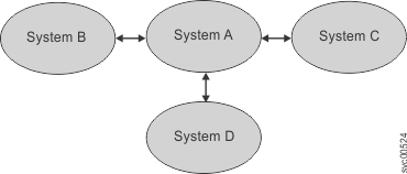
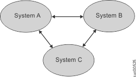
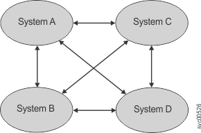


The following examples show Fibre Channel and IP partnerships that can be established with Lenovo Storage V7000clustered systems.


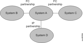
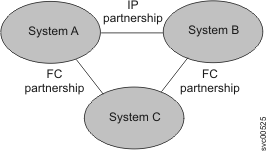
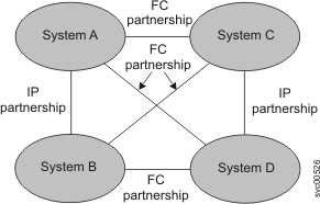


For more information on how to configure and deploy systems with IP partnerships, see "Configuring IP partnerships."
To establish a Metro Mirror and Global Mirror partnership between two systems that are connected through Fibre Channel connections, you must run the mkfcpartnership command from both systems. For example, to establish a partnership between system A and system B, you must run the mkfcpartnership command from system A and specify system B as the remote system. At this point, the partnership is partially configured and is sometimes described as one-way communication. Next, you must run the mkfcpartnership command from system B and specify system A as the remote system. When this command completes, the partnership is fully configured for two-way communication between the systems.If the local and remote system uses IP connections, you need to issue the mkippartnership command on both the local and remote system to fully configure the partnership. You can also use the management GUI to create Metro Mirror and Global Mirror partnerships.
- Partially Configured: Local (partially_configured_local)
- Indicates that only the local system has the partnership defined. For the displayed system to be fully configured and to complete the partnership, you must define the system partnership from the system that is displayed to this system. You can do this by issuing the mkfcpartnership command for Fibre Channel connections, issuing the mkippartnership command for IP connections, or by using the management GUI on the remote system.
- Fully Configured (fully_configured)
- Indicates that the partnership is active on the local and remote system and is started.
- Not Present (not_present)
- Indicates the remote system is not visible. This could be caused by a problem with the connectivity between the local and remote system or by the remote system being inactive.
- Partially Configured: Local Stopped (partially_configured_local_stopped)
- Indicates that only the local system has the partnership defined,
and the partnership has been stopped on the local system.Note: It is the partnership that is stopped, not the system.
- Fully Configured: Stopped (fully_configured_stopped)
- Indicates that both the local system and the remote system have
the partnership defined, and the partnership has been stopped on the
local system.Note: It is the partnership that is stopped, not the system.
- Fully Configured: Remote Stopped (fully_configured_remote_stopped)
- Indicates that both the local system and the remote system have
the partnership defined, and the partnership has been stopped on the
remote system.Note: It is the partnership that is stopped, not the system.
- Fully Configured: Local Excluded (fully_configured_local_excluded)
- Indicates that both the local system and the remote system have the partnership defined; however, the local system is currently excluding the link to the remote system. This state usually occurs when the link between the two systems has been compromised by too many errors or slow response times of the partnership.
- Fully Configured: Remote Excluded (fully_configured_remote_excluded)
- Indicates that both the local system and the remote system have the partnership defined; however, the remote system is currently excluding the link to the local system. This state usually occurs when the link between the two systems has been compromised by too many errors or slow response times of the partnership.
- Fully Configured: Exceeded (fully_configured_exceeded)
- Indicates that both the local system and the remote system have the partnership defined; however, the partnership is disabled because the network of systems exceeds the number of systems allowed in partnerships. To resolve this error, reduce the number of systems that are partnered in this network. Partnerships can be defined between up to four systems in a network.
In addition to Fibre Channel and Fibre Channel over Ethernet (FCoE) connections, Metro Mirror and Global Mirror partnerships can be established over Ethernet links using the IPv4 and IPv6 addresses associated with Ethernet ports. These IP partnerships can be connections through Ethernet switches, or direct connections between local and partner systems. Partnerships must be created as either an IPv4 or IPv6 partnership.
Remote-copy groups are unique to IP partnerships and contain local and remote IP addresses accessible to each other through an IP partnership. A remote-copy group must contain at least one IP address in the local system and one IP address in the remote system. You must create the remote-copy groups before establishing the IP partnership.
Each Ethernet port can be associated with two IP addresses; one using IPv4 addressing and the other using IPv6. Use either IPv4 or IPv6 for IP partnership. You should configure more than two IP addresses within one system of the remote-copy group to allow for IP connection failover if the local or partner system experiences a node or port failure.
To change Metro Mirror and Global Mirror partnerships, use the chpartnership command. To delete Metro Mirror and Global Mirror partnerships, use the rmpartnership command.
Background copy management
In a multiple-cycling Global Mirror copy, the linkbandwidthmbits parameter of the mkfcpartnership and mkippartnership commands controls the rate at which updates are propagated to the remote system. To ensure that the remote copies are as similar as possible to the local copies, the bandwidth parameter needs to be at least the average rate that write operations are applied to all volumes that are replicated by using multiple-cycling Global Mirror across this partnership. For optimum remedial process optimization (RPO), keep the bandwidth parameter less than the actual available bandwidth to ensure that multiple-cycling Global Mirror relationships do not congest the fabric. Also leave sufficient bandwidth for Metro Mirror and noncycling Global Mirror relationships to support their I/Os that are being replicated.
Using CHAP with an IP partnership (optional)
- Select , then select .
- Select .
Before creating an IP partnership, define a CHAP secret for each system, then configure CHAP to be used for IP partnerships on each system.
For example, when creating an IP partnership that uses CHAP between system A and system B, first define a CHAP secret on each system. The CHAP secret value on systems A and B can differ. On system A, specify the system B CHAP secret in the Create Partnership or Partnership Properties dialog, then on system B, specify the system A CHAP secret using one of the dialogs.
When creating an IP partnership on a local system using CHAP, if you do not specify the system-wide CHAP secret of the partner system, the local system displays a CHAP authentication failure message. If an IP partnership using CHAP is active, you must stop the partnership before modifying the CHAP configuration.
Metro Mirror and Global Mirror between SAN Volume Controller and other Storwize® family systems
You can create partnerships with SAN Volume Controller and other Storwize family systems to allow Metro Mirror and Global Mirror to operate between the two systems. To be able to create these partnerships, clustered systems must be at version 6.3.0 or later.
A clustered system is in one of two layers: the replication layer or the storage layer. The SAN Volume Controller system is always in the replication layer. To create partnerships with SAN Volume Controller, a system must be in replication layer.
A Storwize family system is in the storage layer by default, but the system can be configured to be in the replication layer instead.
