When you create and configure IP partnerships, consider the following requirements and constraints:
Supported IP partnership configurations
The following general configurations are supported, but the number of I/O groups that are configured for each site can be different.
Configuration 1: In this configuration, only a single intersite link is available. Therefore, only a one remote copy port group is configured on each node.
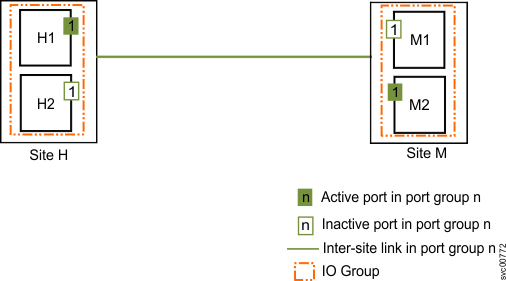
Only one port from either of the nodes in each system actively participates in the IP partnership. The other port acts as the failover port. If a critical failure is observed on node H1 in Site H, the IP partnership will fail over to node H2 and continue. Remote copy relationships might stop momentarily during the failover.
Configuration 2: In this configuration, only one intersite link is available. Both I/O groups in each system have a single remote-copy port group configured on each node. However, out of all of the available ports, only one port from either of the nodes in each system actively participates in the IP partnership. The other ports act as failover ports.
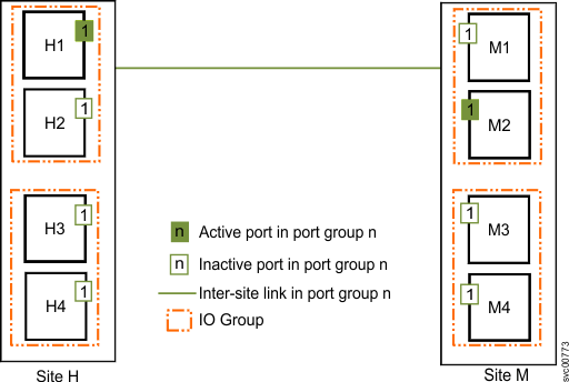
If a critical failure is observed on node H1 in Site H, the IP partnership fails over to node H2, H3, or H4 and continues. Remote copy relationships might stop momentarily during the failover.
Configuration 3: In this configuration, eight-node systems are available. However, only two I/O groups are supported in IP partnerships. Both I/O groups in each system have a single remote-copy port group configured on each node. However, out of all the available ports, only one port from either node in each system actively participates in IP partnership. The other ports act as failover ports.
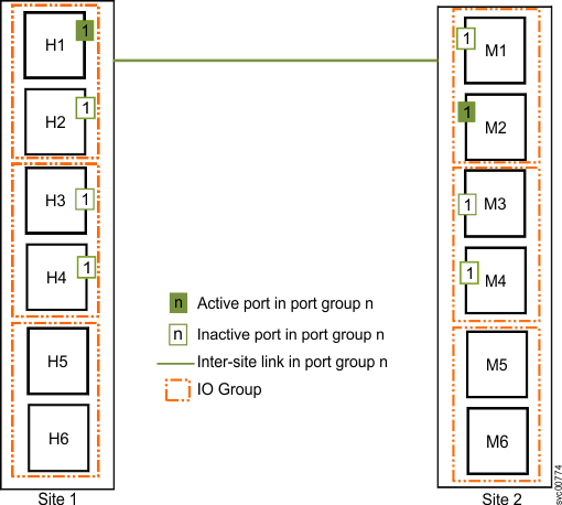
If a critical failure is observed on node H1 in Site 1, the IP partnership fails over to node H2, H3, or H4 and continues. Remote copy relationships might stop momentarily during the failover.
Configuration 4: In this configuration, two intersite links are available; therefore, two remote-copy port groups are configured. One port from each node in each system actively participates in the IP partnership. If a critical failure is observed on node H1 in Site H, the IP partnership continues over the other port on node H2.
No failure occurs in this scenario; however, the effective bandwidth is reduced to half; only one of the two links is available to facilitate IP partnership traffic. When the failure is corrected, ports will fail back and the IP partnership continues to operate over both links.
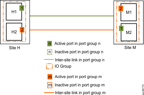
Configuration 5: In this multi-node configuration, two intersite links are available; two remote-copy port groups are configured. Four ports (one per node) are configured in remote-copy port groups "1" and "2". Out of the four ports, only two ports actively facilitate the IP partnerships. This port and path selection is maintained by an internal algorithm. The other ports act as failover ports.
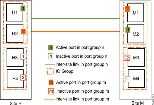
If a critical failure occurs on node H1 in Site H, the IP partnership will fail over to node H3 and continue. The link bandwidth is not affected, as the failover happens immediately and completes quickly while IP partnership traffic continues from node H2.
Configuration 6: In this configuration, eight node systems are available. However, only two I/O groups are currently supported for IP partnerships. Both I/O groups in each system have four ports (one per node) configured in remote-copy port groups "1" and "2". Out of the four ports, only two ports actively facilitate the IP partnerships. This port and path selection is maintained by an internal algorithm. The other ports act as failover ports.
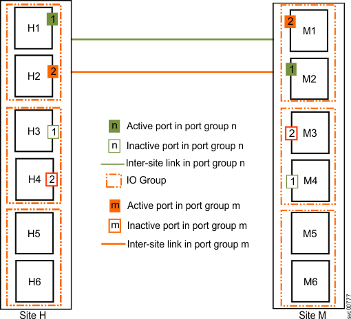
If a critical failure is observed on the node H1 in Site H, the IP partnership will fail over to node H3 and continue. The link bandwidth is not affected because the failover happens immediately and completes quickly while IP partnership traffic continues from node H2. The other I/O groups, or all the I/O groups, can be connected over a Fibre Channel partnership with another system.