Expansion canisters can be optionally connected to systems.
Expansion canisters do not have any controls. As Rear view of expansion canister shows, each expansion canister has two SAS ports and several LED indicators. Each SAS port is a mini-SAS HD socket. SAS cables should be plugged in with the blue release tag oriented below the connector.

- 1 SAS port 1 (inbound)
- 2 SAS port 2 (outbound)
- 3 Service port
Inbound SAS port 1 must be connected. This port 1 is used to connect the expansion enclosure to the system control enclosure. The expansion enclosure can be directly connected to the control enclosure or it can be chained through other expansion enclosures.
Outbound SAS port 2 is optional. This port 2 is used to connect this expansion enclosures to other expansion enclosures in the chain.
The Service port 3 should not be connected to any SAS cables.
Expansion canister LED indicators
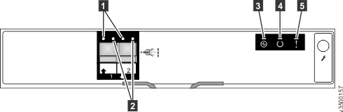
- 1 Link LED(x2–one per port)
- 2 Fault LED (x2–one per port)
- 3 Expansion canister power LED
- 4 Expansion canister status LED
- 5 Expansion canister fault LED
SAS port LED status summarizes the values of the LEDs on the SAS ports and links on a system expansion canister. A SAS link consists of four lanes, called phys.
| Name | Callout | Symbol | Color | State | Meaning |
|---|---|---|---|---|---|
| Link | 1 | None | Green | OFF | No link connection on any phy. |
| ON | There is a connection on at least one phy. | ||||
| Fault | 2 | None | Amber | OFF | No fault. All four phys have a link connection. |
| ON | This can indicate a number of different error
conditions: |
Expansion canister LED status summarizes the LED status values on a system expansion canister.
| Name | Callout | Symbol | Color | State | Meaning |
|---|---|---|---|---|---|
| Power | 3 |  |
Green | OFF | No power is available. |
| ON | Power is available. | ||||
| Status | 4 |  |
Green | OFF | The system code has not started, the system is off, in standby, or self test. |
| BLINK | The canister is unable to read data from the midplane. | ||||
| ON | The canister machine code is active. | ||||
| Canister fault | 5 |  |
Amber | OFF | No faults requiring part replacement have been detected on the expansion canister. |
| BLINK | The canister is being identified. There might or might not be a fault condition. | ||||
| ON | Either there is a fault which requires part replacement or the canister is still starting. |