2.5-inch model
There are the right EIA assembly and the left EIA assembly on the server, use the following steps to replace them.
For the right EIA assembly
- Read the safety information that begins on Safety and Installation guidelines.
- Turn off the server and peripheral devices, and disconnect the power cord and all external cables.
- Remove the top cover (see Removing the top cover).
- Remove the fan cage (see Removing the fan cage assembly).
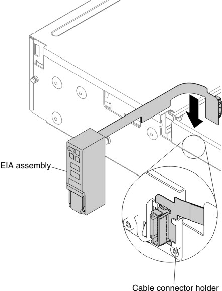
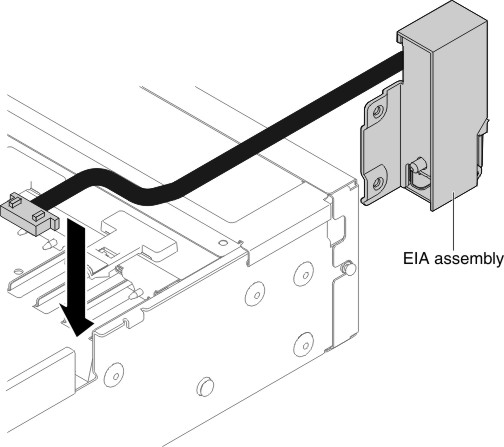
- Insert the cable connector into the cable connector holder.Figure 1. Cable connector installation
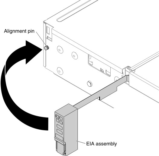
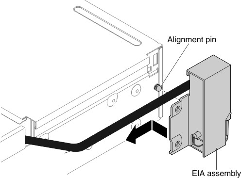
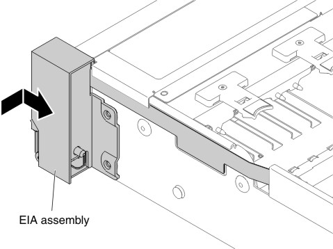
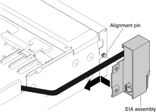
- Align the EIA assembly with the alignment pin.Figure 2. EIA assembly alignment
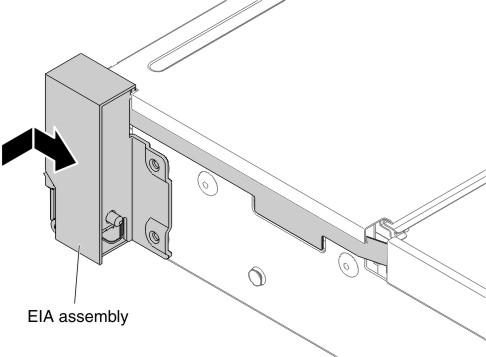
- Push the EIA assembly slightly toward the rear of the server to
fix the EIA assembly on the server.Figure 3. EIA assembly installation
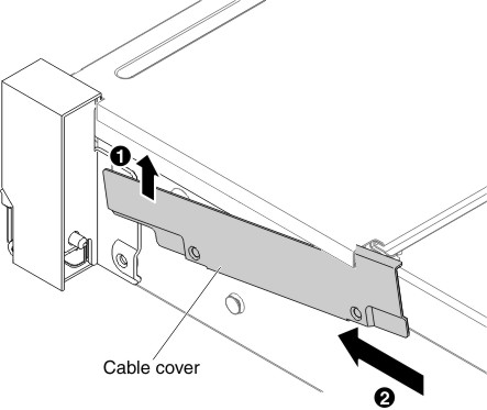
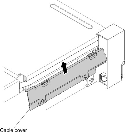
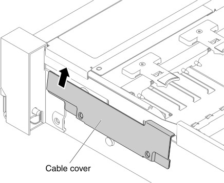
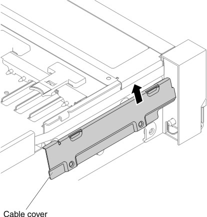
- Tilt and install the cable cover.Figure 4. Cable cover installation
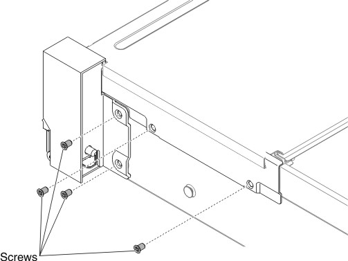
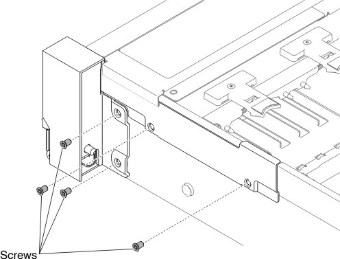
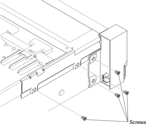
- Fasten screws.Figure 5. Screw installation
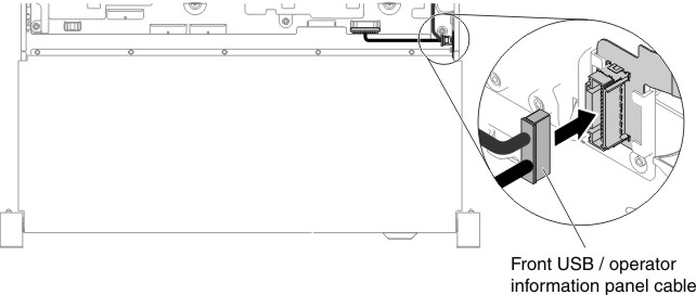
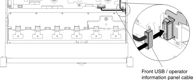
- Connect the front USB/operator information panel cables to the
system board and the connector mounted on the chassis side wall.Figure 6. Cable connection
- Replace the fan cage assembly (see Replacing the fan cage assembly).
- Replace the top cover (see Replacing the top cover).
- Slide the server into the rack.
- Reconnect the power cords and any cables that you removed.
- Turn on the peripheral devices and the server.
For the left EIA assembly
- Read the safety information that begins on Safety and Installation guidelines.
- Turn off the server and peripheral devices, and disconnect the power cord and all external cables.
- Remove the top cover (see Removing the top cover).
- Remove the fan cage assembly (see Removing the fan cage assembly).
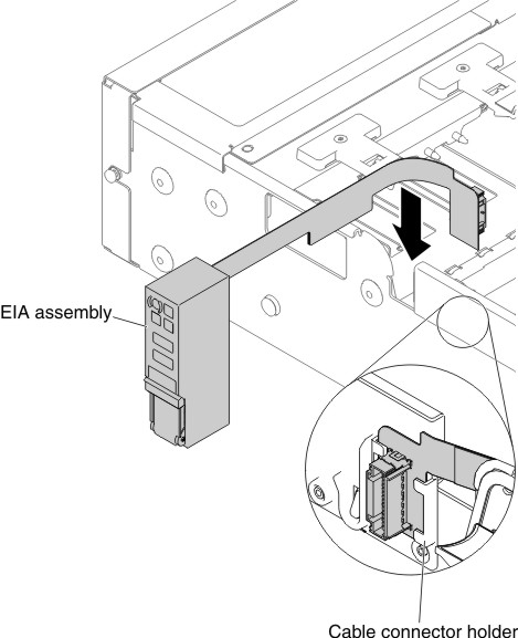
- Route the cable into the slot.Figure 7. Cable routing
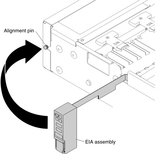
- Align the EIA assembly with the alignment pin and push it slightly
toward the rear of the server fix the EIA assembly on the server.Figure 8. EIA assembly alignment
- Tilt and install the cable cover.Figure 9. Cable cover installation
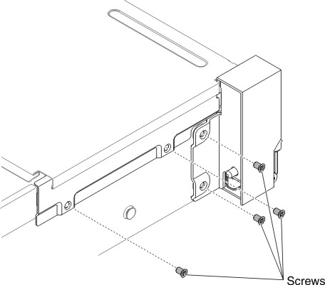
- Fasten screws.Figure 10. Screw installation
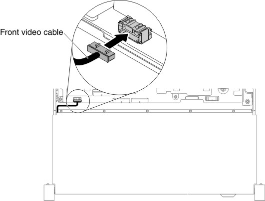
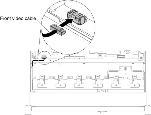
- Connect the front video cable to the system board.Figure 11. Cable connection
- Replace the fan cage assembly (see Replacing the fan cage assembly).
- Replace the top cover (see Replacing the top cover).
- Slide the server into the rack.
- Reconnect the power cords and any cables that you removed.
- Turn on the peripheral devices and the server.